Mitsubishi Lancer Evolution IX. Manual - part 512


  Index      Mitsubishi     Mitsubishi Lancer Evolution IX - service repair manual


Search            


Content   ..  510  511  512  513   ..


Mitsubishi Lancer Evolution IX. Manual - part 512


TROUBLESHOOTING

ANTI-SKID BRAKING SYSTEM (ABS)

35B-79

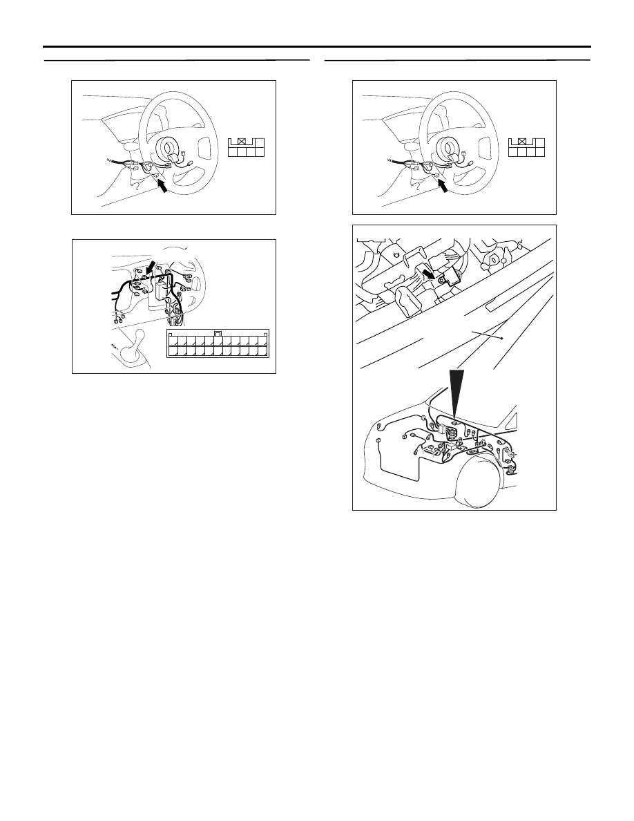
STEP 6. Check the following connectors.

Steering wheel sensor connector C-230

Joint connector C-06
Check the connectors for loose, corroded or dam-
aged terminals, or terminals pushed back in the con-
nector.

Q: Are the connectors and terminals in good 

condition?
YES : 

Go to Step 7.

NO : 

Repair it and then go to Step 11.

STEP 7. Check the following harness wires.

The wire between steering wheel sensor connector 
C-230 (terminal 3) and earth

Q: Is any harness wire damaged?

YES : 

Repair or replace it and then go to Step 11.

NO : 

Go to Step 11.

AC311196AB

Connector: C-230

Harness side

5 4

1
2

3

AC311161AF

Connector: C-06

C-06 (GR)

2

1

3

13

12

14

21

10

5

4

6

16

15

17

7 8 9

19

18

20

11

22

AC311196AB

Connector: C-230

Harness side

5 4

1
2

3

AC311200AB

Earth

Windshield
wiper arm

TROUBLESHOOTING

ANTI-SKID BRAKING SYSTEM (ABS)

35B-80

STEP 8. Check steering wheel sensor output 
voltage.

(1) Connect steering wheel sensor connector C-230.
(2) Turn the ignition switch to the "ON" position.

(3) Measure the voltage, by backprobing, between 

terminal 1 and earth, terminal 4 and earth, and 
terminal 5 and earth.

OK: The voltage should measure as indi-
cated in the figure.

Q: Is the steering wheel sensor output voltage 

normal?
YES : 

Go to Step 9.

NO : 

Replace the steering wheel sensor (Refer to 

P.35B-150

). Then go to Step 11.

STEP 9. Check the following connectors.

Steering wheel sensor connector C-230

Intermediate connector C-138

ABS-ECU connector B-118
Check the connectors for loose, corroded or dam-
aged terminals, or terminals pushed back in the con-
nector.

Q: Are the connectors and terminals in good 

condition?
YES : 

Go to Step 10.

NO : 

Repair it and then go to Step 11.

AC311195AD

Connector: C-230

Connector C-230
(Harness side)

5 4

1
2

3

AC211894

Time

AB

Voltage

2.7 - 4.4 V

0.8 - 2.1 V

Variations in voltage when turning the
steering wheel 

AC311196AB

Connector: C-230

Harness side

5 4

1
2

3

AC311160AE

Connector: C-138

C-138

AC311127AB

B-118 (B)

Connector: B-118

28

32

34

12

11

33

30

21

9

10

22

31

7

8

29

20 19

24

2

26

4

5

6

27

18 17

3

25

16 15

1

23

13

14

Harness side

TROUBLESHOOTING

ANTI-SKID BRAKING SYSTEM (ABS)

35B-81

STEP 10. Check the following harness wires.

If diagnosis code No.81 (ST-1) is set: The wire 

between steering wheel sensor connector C-230 
(terminal 5) and ABS-ECU connector B-118 (ter-
minal 26)

• If diagnosis code No.82 (ST-2) is set: The wire 

between steering wheel sensor connector C-230 
(terminal 4) and ABS-ECU connector B-118 (ter-
minal 17)

• If diagnosis code No.83 (ST-N) is set: The wire 

between steering wheel sensor connector C-230 
(terminal 1) and ABS-ECU connector B-118 (ter-
minal 4)

Q: Is any harness wire damaged?

YES : 

Repair or replace it and then go to Step 11.

NO : 

Replace the brake modulator hydraulic unit 
(integrated with ABS-ECU) (Refer to 

P.35B-143

). Then go to Step 11.

STEP 11. Check whether the diagnosis code is 
reset.

Check again if the diagnosis code is set.
(1) Turn the ignition switch to the "ON" position.
(2) Erase the diagnosis code.
(3) Turn the ignition switch to the "LOCK" (OFF) 

position.

(4) Turn the ignition switch to the "ON" position.
(5) Check if the diagnosis code is set.
(6) Turn the ignition switch to the "LOCK" (OFF) 

position.

Q: Does diagnosis code No.81, 82 and/or 83 reset?

YES : 

Return to Step 1.

NO : 

The procedure is complete.

AC311196AB

Connector: C-230

Harness side

5 4

1
2

3

AC311127AB

B-118 (B)

Connector: B-118

28

32

34

12

11

33

30

21

9

10

22

31

7

8

29

20 19

24

2

26

4

5

6

27

18 17

3

25

16 15

1

23

13

14

Harness side

AC311157

Steering shaft

AB

MB991502

<Using the M.U.T.-II>

AC311153

AB

MB991911

16-PIN

MB991827

MB991824 

<Using the M.U.T.-III>

TROUBLESHOOTING

ANTI-SKID BRAKING SYSTEM (ABS)

35B-82

INSPECTION CHART FOR TROUBLE 
SYMPTOMS

M1352011400750

NOTE: If steering movements are made when driv-
ing at high speed, or when driving on road surfaces 
with low frictional resistance, or when passing over 
bumps, the ABS may operate although sudden brak-
ing is not being applied. Because of this, when get-
ting information from the customer, check if the 
problem occurred while driving under such condi-
tions as these.

NOTE: During ABS operation, the brake pedal may 
vibrate a little or may not be able to be pressed. Such 
conditions are due to intermittent changes in hydrau-
lic pressure inside the brake line to prevent the 
wheels from locking. This is normal.

Trouble symptoms

Inspection procedure 
No.

Reference page

Communication between the M.U.T.-II/III and all the 
system is not possible.

1

<LH drive vehicle> 

P.35B-83

, <RH drive 

vehicle> 

P.35B-109

Communication between the M.U.T.-II/III and the 
ABS-ECU is not possible.

2

<LH drive vehicle> 

P.35B-87

, <RH drive 

vehicle> 

P.35B-113

When the ignition key is turned to the "ON" position 
(Engine stopped), the ABS warning lamp does not 
illuminate.

3

<LH drive vehicle> 

P.35B-92

, <RH drive 

vehicle> 

P.35B-118

The ABS warning lamp remains illuminated after the 
engine is started.

4

<LH drive vehicle> 

P.35B-97

, <RH drive 

vehicle> 

P.35B-123

In the inspection with the M.U.T.-II/III data list, the 
parking brake switch is not turned ON or turned OFF.

5

<LH drive vehicle> 

P.35B-99

, <RH drive 

vehicle> 

P.35B-125

The neutral position learning of the steering wheel 
sensor is not detected.

6

<LH drive vehicle> 

P.35B-103

, <RH drive 

vehicle> 

P.35B-129

Faulty ABS operation

7

<LH drive vehicle> 

P.35B-108

, <RH drive 

vehicle> 

P.35B-134


Content   ..  510  511  512  513   ..