Mitsubishi Lancer Evolution IX. Manual - part 488
AC000872
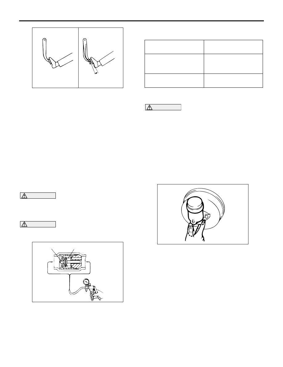
Good
No good
AB
ON-VEHICLE SERVICE
SERVICE BRAKES
35A-7
(3) With the engine running, step on the brake
pedal and then stop the engine. Hold the
pedal depressed for 30 seconds. If the pedal
height does not change, the booster is in good
condition, if the pedal rises, the booster is
defective.
2. If the above three tests are okay, the booster is
OK. If one of the above three tests is not okay, the
check valve, vacuum hose, or booster is
defective. Check the check valve operation (Refer
to
), vacuum hose for leaks, high volume
engine vacuum applied to booster. Repair or
replace as necessary. If these are OK, replace the
booster and repeat this test starting at Step 1.
CHECK VALVE OPERATION CHECK
M1351009000462
CAUTION
The check valve should not be removed from the
vacuum hose.
1. Remove the vacuum hose (Refer to
).
CAUTION
If the check valve is defective, replace it as an
assembly unit together with the vacuum hose.
AC000873AE
A
B
Valve
Spring
Intake manifold
side
(does not hold)
Booster side
(holds)
2. Check the operation of the check valve by using a
vacuum pump.
Vacuum pump
connection
Accept/reject criteria
Connection at the brake
booster side (A)
A negative pressure
(vacuum) is created and
held.
Connection at the intake
manifold side (B)
A negative pressure
(vacuum) is not created.
BLEEDING
M1351001400552
CAUTION
Use only brake fluid DOT 3 or DOT 4. Never mix
the specified brake fluid with other fluid as it will
affect the braking performance significantly.
MASTER CYLINDER BLEEDING
The master cylinder has no check valve, so if bleed-
ing is carried out by the following procedure, bleed-
ing of air from the brake pipeline will become easier
(When brake fluid is not contained in the master cyl-
inder).
1. Fill the reserve tank with brake fluid.
2. Keep the brake pedal depressed.
AC000876
3. Have another person cover the master cylinder
outlet with a finger.
4. With the outlet still closed, release the brake
pedal.
5. Repeat steps 2
− 4 three or four times to fill the
inside of the master cylinder with brake fluid.