Mitsubishi Lancer Evolution IX. Manual - part 382


  Index      Mitsubishi     Mitsubishi Lancer Evolution IX - service repair manual


Search            


Content   ..  380  381  382  383   ..


Mitsubishi Lancer Evolution IX. Manual - part 382


GENERAL INFORMATION

MULTIPORT FUEL INJECTION (MPI)

13A-3

OTHER CONTROL FUNCTIONS

1. Fuel Pump Control

Turns the fuel pump relay ON so that current is sup-

plied to the fuel pump while the engine is crank-
ing or running.

2. A/C Relay Control

Turns the compressor clutch of the A/C ON and OFF.

3. Oil feeder control valve control

The engine-ECU effects duty cycle control on the 

engine oil feeder control valve, in accordance 
with the engine speed. This regulates the supply 
of engine oil to the intake rocker starft, which 
switches the cams.

4. Fan Motor Control

The revolutions of the radiator fan and condenser fan 

are controlled in response to the engine coolant 
temperature and vehicle speed.

5. Purge Control Solenoid Valve Control 

(Refer to GROUP 17 

− Engine And Emission Control 

− Evaporative Emission Control System 

P.17-9

).

6. EGR Control Solenoid Valve Control 

(Refer to GROUP 17 

− Engine And Emission Control 

− Exhaust Gas Recirculation (EGR) System 

P.17-13

).

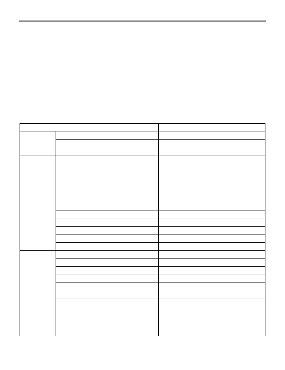
GENERAL SPECIFICATIONS

Items

Specifications

Throttle body

Throttle bore mm

60

Throttle position sensor

Variable resistor type

Idle speed control servo

Stepper motor type

Engine-ECU

Identification No.

E6T46983

Sensors

Air flow sensor

Karman vortex type

Barometric pressure sensor

Semiconductor type

Intake air temperature sensor

Thermistor type

Engine coolant temperature

Thermistor type

Oxygen sensor 

Zirconia type

Vehicle speed sensor

Magnetic resistive element type

Intake camshaft position sensor

Hall element type

Exhaust camshaft position sensor

Hall element type

Crank angle sensor

Hall element type

Detonation sensor

Piezoelectric type

Power steering fluid pressure switch

Contact switch type

Actuators

Engine control relay type

Contact switch type

Fuel pump relay type

Contact switch type

Injector type and number

Electromagnetic type, 4

Injector identification mark

MDL 560P

Oil feeder control valve

Duty cycle type solenoid valve

EGR control solenoid valve

Duty cycle type solenoid valve

Purge control solenoid valve 

Duty cycle type solenoid valve

Fuel pressure control solenoid valve

ON/OFF type solenoid valve

Waste gate solenoid valve

Duty cycle type solenoid valve

Fuel pressure 
regulator

Regulator pressure kPa

294

GENERAL INFORMATION

MULTIPORT FUEL INJECTION (MPI)

13A-4

MULTI-POINT FUEL INJECTION SYSTEM DIAGRAM

AK501871

Canister

5 Throttle position sensor

2 Idle speed control servo 
   (Stepper motor)

Check valve

By-pass valve

6 Purge control 
   solenoid valve

3 Fuel pressure control
   solenoid valve

9 Barometric 
   pressure sensor

Fuel pressure
regulator

To fuel tank

6 Intake camshaft 
   position sensor

From fuel pump

4 Intake air 
   temperature 
   sensor

3 Air flow sensor

Air 
inlet

4 Waste gate solenoid valve

1 Oxygen
   sensor (front)

Waste gate actuator

Catalytic converter

Catalytic converter

2 Oxygen sensor (rear)

11 Detonation sensor

8 Crank angle sensor

10 Engine coolant temperature sensor

1 Injector

EGR 
valve

5 EGR
   control 
   solenoid
   valve

AB

7 Exhaust camshaft 
   position sensor

7 Oil feeder
   control valve

1   Oxygen sensor (front)
2   Oxygen sensor (rear)
3   Air flow sensor
4   Intake air temperature 
     sensor
5   Throttle position 
     sensor
6   Intake camshaft
     position sensor
7   Exhaust camshaft
     position sensor
8   Crank angle sensor
9   Barometric pressure 
     sensor
10 Engine coolant 
     temperature sensor
11 Detonation sensor

Power supply
Ignition switch-IG
Ignition switch-ST
A/C switch
A/C load signal
Power steering 
fluid pressure 
switch
Alternator FR 
terminal
Clutch switch
Transmission oil 
temperature sensor
Vehicle speed
sensor

Engine-
ECU

1  Injector
2  Idle speed control 
    servo (Stepper 
    motor)
3  Fuel pressure 
    control solenoid 
    valve
4  Waste gate 
    solenoid valve
5  EGR control 
    solenoid valve
6  Purge control 
    solenoid valve
7  Oil feeder control
    valve

Engine control relay
Fuel pump relay 2 
Fuel pump relay 3
A/C relay
Ignition coil
Fan controller
Condenser fan relay(High)
Condenser fan relay(Low)
Engine warning lamp
Diagnosis output
Alternator G terminal
Air flow sensor reset 
signal
Oxygen sensor heater
(Front)
Oxygen sensor heater
(Rear)
Tachometer
Transmission oil
temperature warning lamp

SERVICE SPECIFICATIONS

MULTIPORT FUEL INJECTION (MPI)

13A-5

SERVICE SPECIFICATIONS

M1131000301452

Items

Specifications

Basic idle speed r/min

800 

± 50

Throttle position sensor adjusting voltage mV

535 

− 735

Throttle position sensor resistance k

3.5 

− 6.5

Idle speed control servo coil resistance (at 20

°C) Ω

28 

− 33

Intake air temperature sensor 
resistance k

−20°C

13 

− 17

0

°C

5.3 

− 6.7

20

°C

2.3 

− 3.0

40

°C

1.0 

− 1.5

60

°C

0.56 

− 0.76

80

°C

0.30 

− 0.42

Engine coolant temperature 
sensor resistance k

−20°C

14 

− 17

0

°C

5.1 

− 6.5

20

°C

2.1 

− 2.7

40

°C

0.9 

− 1.3

60

°C

0.48 

− 0.68

80

°C

0.26 

− 0.36

Oxygen sensor output voltage (at racing) V

0.6 

− 1.0

Oxygen sensor heater 
resistance (at 20

°C) Ω

Front

4.5 

− 8.0

Rear

11 

− 18

Fuel pressure kPa

Vacuum hose disconnection

289 

− 309 at curb idle

Vacuum hose connection

Approximately 230 at curb idle

Fuel pressure control solenoid valve resistance (at 20

°C) Ω

28 

− 36

Fuel pump resistance 

0.45 

− 0.65

Injector coil restance (at 20

°C) Ω

− 3

Injector fuel leakage rate Drop/minute

1 or less

Resistor (for injector) resistance (at 20

°C) Ω

5.8 

− 6.2

Oil feeder control valve (at 20

°C) Ω

6.9 

− 7.2

SPECIAL TOOLS

MULTIPORT FUEL INJECTION (MPI)

13A-6

SPECIAL TOOLS

M1131000601583

Tool

Number

Name

Use

MB991502

M.U.T.-II sub assembly

• Reading diagnosis code

• MPI system inspection

• Measurement of fuel pressure

MB991955

A: MB991824
B: MB991827
C: MB991910
D: MB991911
E: MB991825
F: MB991826

M.U.T.-III sub assembly

A: Vehicle communication 

interface (V.C.I.)

B: M.U.T.-III USB cable
C: M.U.T.-III main harness 

A (Vehicles with CAN 
communication system)

D: M.U.T.-III main harness 

B (Vehicles without CAN 
communication system)

E: M.U.T.-III measurement 

adapter

F: M.U.T.-III trigger harness

• Reading diagnosis code

• MPI system inspection

• Measurement of fuel pressure

CAUTION

If you connect M.U.T.-III main 
harness A to a vehicle without 
CAN communication system to 
use the M.U.T.-III, a pulse signal 
may interfere with the 
simulated vehicle speed lines, 
thus causing the M.U.T.-III 
inoperative. Therefore, use the 
M.U.T.-III main harness B 
(MB991911) instead.

MB991348

Test harness set

• Inspection using an 

oscilloscope

B991502

MB991910

MB991826

MB991955

MB991911

MB991824

MB991827

MB991825

A

B

C

D

E

F

DO NOT USE

MB991348


Content   ..  380  381  382  383   ..