Mitsubishi Lancer Evolution IX. Manual - part 335
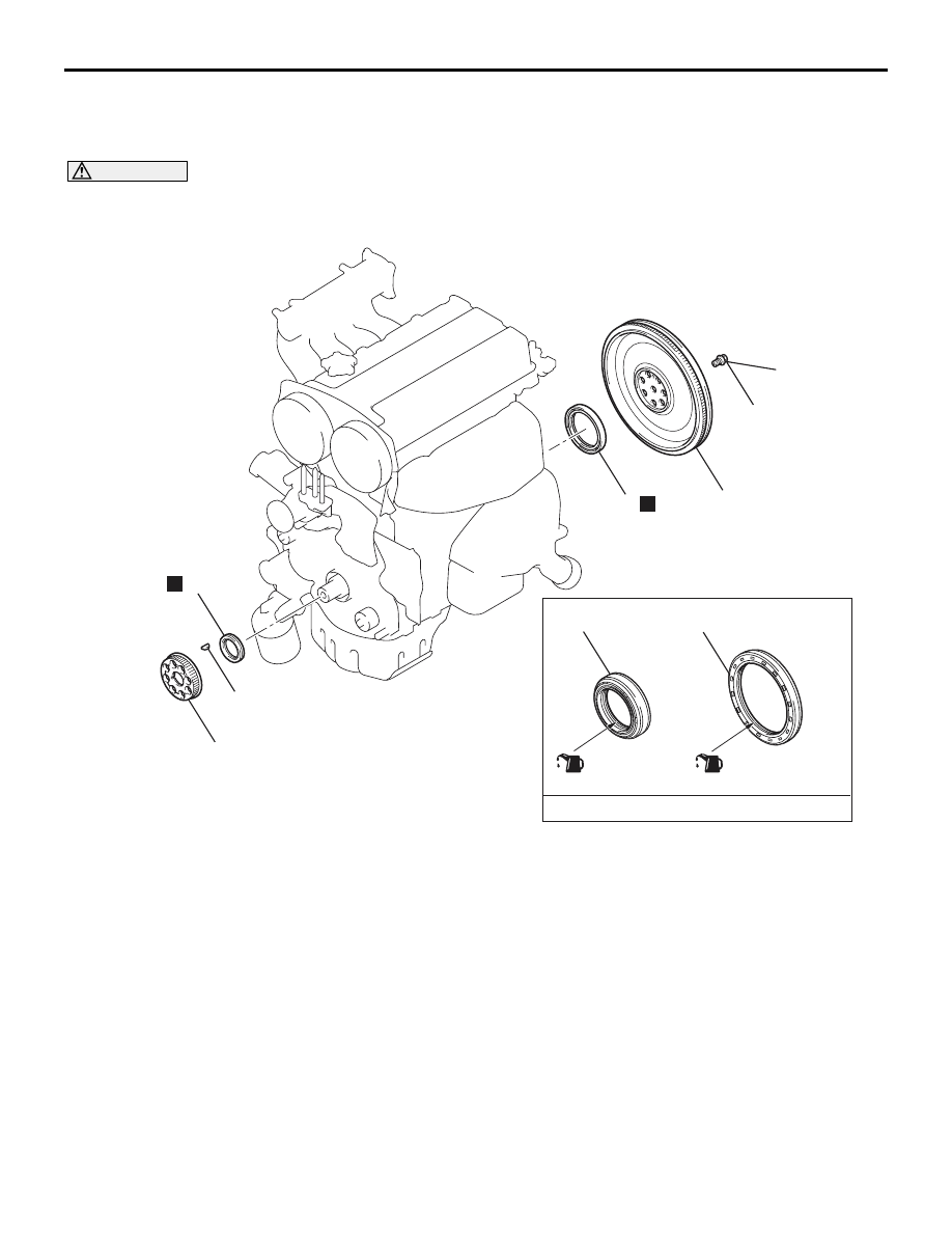
CRANKSHAFT OIL SEAL
ENGINE MECHANICAL
11A-29
CRANKSHAFT OIL SEAL
REMOVAL AND INSTALLATION
M1112003100444
CAUTION
If the vehicle is equipped with the Brembo
™ disc brake, during maintenance, take care not to contact
the parts or tools to the caliper because the paint of caliper will be scratched.
AC210943
AB
1
2
3
(Lip section)
Engine oil
3
6
6
5
4
N
N
132 ± 5 N·m
(Lip section)
Crankshaft front oil seal removal
steps
•
Valve timing belt, balancer timing
belt (Refer to
).
>>
D
<<
1.
Crankshaft balancer shaft drive
sprocket
2.
Crankshaft key
>>
C
<<
3.
Crankshaft front oil seal
Crankshaft front oil seal removal
steps
•
Transfer assembly (Refer to
GROUP 22A, Transfer Assembly
).
•
Transmission assembly (Refer to
GROUP 22A, Transmission
Assembly
).
<<
A
>>
>>
B
4.
Flywheel bolts
5.
Flywheel assembly
>>
A
6.
Crankshaft rear oil seal