Mitsubishi Lancer Evolution IX. Manual - part 327


  Index      Mitsubishi     Mitsubishi Lancer Evolution IX - service repair manual


Search            


Content   ..  325  326  327  328   ..


Mitsubishi Lancer Evolution IX. Manual - part 327


POWER STEERING HOSES

POWER STEERING

37-33

POWER STEERING HOSES

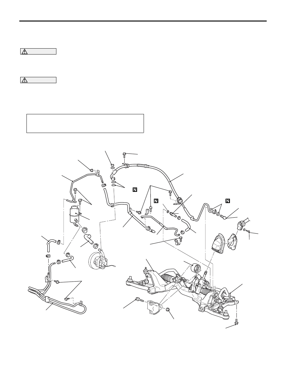
REMOVAL AND INSTALLATION

M1372005700828

WARNING

Before removing the steering gear, refer to GROUP 52B, Service Precautions (

P.52B-3

) and 

Air Bag Module and Clock Spring (

P.52B-110

). Centre the front wheels. Failure to do so may 

damage the SRS clock spring and render the SRS system inoperative, risking serious injury.

CAUTION

• During maintenance, take care not to contact the parts or tools to the caliper because the paint of 

caliper will be scratched. And if there is brake fluid on the caliper, wipe out quickly.

Pre-removal and Post-installation Operation
• Power Steering Fluid Draining and Refilling (Refer to 

P.37-10

) and Bleeding (Refer to 

P.37-10

).

*

: Indicates parts which should be initially tightened, and then fully tightened after placing the 

vehicle horizontally and loading the full weight of the engine on the vehicle body.

<LH drive vehicles>

AC211825 AC

12 ± 2 N·m

15 ± 3 N·m

12 ± 2 N·m

12 ± 2 N·m

12 ± 2 N·m

12 ± 2 N·m

18 ± 2 N·m

18 ± 3 N·m

59 ± 10 N·m

52 ± 7 N·m*

49 ± 10 N·m

167 ± 9 N·m

Crossmember

14

12

16

17

15

1

5

3

18

11

10

6

9

7

8

12 ± 2 N·m

4

2

13

Removal steps 

1.

Oil reservoir

>>

B

<< 2.

Suction hose

3.

Return hose

4.

Return hose

Removal steps (Continued)

POWER STEERING HOSES

POWER STEERING

37-34

<RH drive vehicles>

AC310935AB

15 ± 3 N·m

18 ± 2 N·m

167 ± 9 N·m

12 ± 2 N·m

49 ± 10 N·m

12 ± 2 N·m

52 ± 7 N·m*

11

1

2

9

10

6

3

7

8

14

Crossmember

12 ± 2 N·m

15

13

59 ± 10 N·m

12 ± 2 N·m

4

12 ± 2 N·m

18 ± 3 N·m

5

12

5.

Return hose

Strut tower bar (Refer to GROUP 42, 
Strut tower bar 

P.42-9

).

6.

Return hose

Clock spring (Refer to GROUP 52B, 
Driver’s, Front Passenger’s Air Bag 
Modules and Clock Spring 

P.52B-110

).

Crossmember Bar (Refer to GROUP 
33, Crossmember Bar 

P.33-17

).

Centremember (Refer to GROUP 32, 
Engine Roll Stopper Centremember 

P.32-7

).

Front exhaust pipe (Refer to GROUP 
15, Exhaust Pipe and Main Muffler 

P.15-13

).

Removal steps (Continued)

7.

Steering gear and joint connecting bolt

8.

Rear roll stopper connecting bolt

9.

Rear roll stopper (Refer to GROUP 32, 
Engine Roll Stopper Centremember 

P.32-7

).

<<

A

>>

10.

Eye bolt

11.

Gasket

>>

B

<< 12.

Pressure hose assembly

>>

A

<< 13.

O-ring

14.

Return hose

15.

Return tube

<<

A

>>

16.

Return tube

17.

O-ring

Front bumper (Refer to GROUP 51, 
Front Bumper Assembly 

P.51-2

).

Intercooler (Refer to GROUP 15, 
Intercooler 

P.15-6

).

18.

Cooler tube assembly

Removal steps (Continued)

Removal steps 

1.

Oil reservoir

>>

B

<< 2.

Suction hose

3.

Return hose

4.

Return hose

Removal steps (Continued)

POWER STEERING HOSES

POWER STEERING

37-35

REMOVAL SERVICE POINT
<<A>> EYE BOLT/RETURN TUBE 
REMOVAL

1. Loosen the crossmember mounting bolts and 

nuts, and lower the crossmember to a position so 
that the eye bolts or return tube at the steering 
gear side can be removed.
NOTE: In this case, do not remove the crossmem-
ber mounting bolts and nuts.

2. Remove the eye bolts or return tube.

INSTALLATION SERVICE POINTS
>>A<< O-RING INSTALLATION

AC311013

1

2

AB

No.

ID 

× Width mm

1

11.0 

× 1.9

2

13.0 

× 1.9

>>B<< PRESSURE HOSE 
ASSEMBLY/SUCTION HOSE REMOVAL

AC211830 AC

Suction hose

Marking

Pressure hose 
assembly

Notch

Install the pressure hose assembly and suction hose 
as illustrated.

5.

Return hose

Strut tower bar (Refer to GROUP 42, 
Strut tower bar 

P.42-9

).

6.

Return hose

Clock spring (Refer to GROUP 52B, 
Driver’s, Front Passenger’s Air Bag 
Modules and Clock Spring 

P.52B-110

).

Crossmember Bar (Refer to GROUP 
33, Crossmember Bar 

P.33-17

).

Centremember (Refer to GROUP 32, 
Engine Roll Stopper Centremember 

P.32-7

).

Front exhaust pipe (Refer to GROUP 
15, Exhaust Pipe and Main Muffler 

P.15-13

).

Removal steps (Continued)

7.

Steering gear and joint connecting bolt

8.

Rear roll stopper connecting bolt

<<

A

>>

9.

Eye bolt

10.

Gasket

>>

B

<< 11.

Pressure hose assembly

>>

A

<< 12.

O-ring

<<

A

>>

13.

Return tube

14.

O-ring

Front bumper (Refer to GROUP 51, 
Front Bumper Assembly 

P.51-2

).

Intercooler (Refer to GROUP 15, 
Intercooler 

P.15-6

).

15.

Cooler tube assembly

Removal steps (Continued)

NOTES


Content   ..  325  326  327  328   ..