Mitsubishi Lancer Evolution IX. Manual - part 270


  Index      Mitsubishi     Mitsubishi Lancer Evolution IX - service repair manual


Search            


Content   ..  268  269  270  271   ..


Mitsubishi Lancer Evolution IX. Manual - part 270


IGNITION SWITCH

CHASSIS ELECTRICAL

54A-17

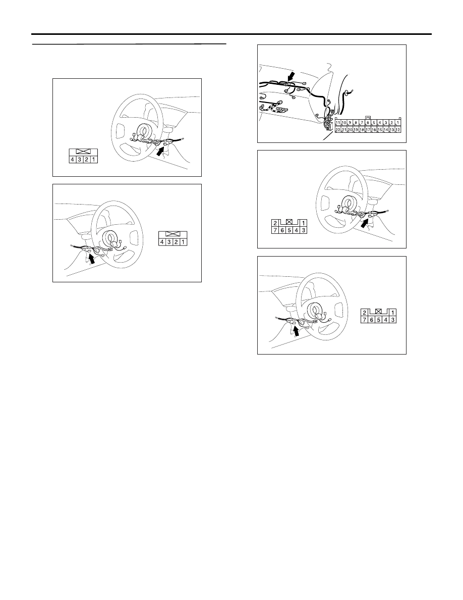
STEP 7. Check the harness wire between 
immobilizer-ECU connector C-207-1 (terminal 4) 
and earth.

AC310479

Connector: C-207-1 <L.H. drive vehicles>

Harness side

AH

AC310481

Connector: C-207-1 <R.H. drive vehicles>

Harness side

AH

AC310452

AX

Connector: C-06
<L.H. drive vehicles>

C-06(GR)

Harness side

AC310479

Connector: C-207 <L.H. drive vehicles>

Harness side

AI

AC310481

Connector: C-207 <R.H. drive vehicles>

Harness side

AI

NOTE: Prior to the wiring harness inspection, check 
joint connector C-06 <LH drive vehicles>, key 
reminder switch connector C-207, and repair if nec-
essary.

Q: Is the harness wire between immobilizer-ECU 

connector C-207-1 (terminal 4) and earth in good 
condition?
YES : 

There is no action to be taken.

NO : 

Repair or replace the damaged 
component(s). Confirm that M.U.T.-II/III 
communicates normally.

IGNITION SWITCH

CHASSIS ELECTRICAL

54A-18

STEP 8. Connector check: immobilizer-ECU 
connector C-207-1 and engine-ECU connector 
C-117

AC504357

AB

Connector: C-117 <L.H. drive vehicles>

Harness side

C-117(GR)

90

77

100

85
96

87

88

89

86

99

9897

75

76

80

81

82

8483

94

95

93

73

74

7978

91

92

71

72

JAE

AC504359

AB

Connector: C-117 <R.H. drive vehicles>

C-117(GR)

Harness side

90

77

100

85
96

87

88

89

86

99

9897

75

76

80

81

82

8483

94

95

93

73

74

7978

91

92

71

72

JAE

AC310479

Connector: C-207-1 <L.H. drive vehicles>

Harness side

AH

AC310481

Connector: C-207-1 <R.H. drive vehicles>

Harness side

AH

Q: Are immobilizer-ECU connector C-207-1 and 

engine-ECU connector C-117 in good condition?
YES : 

Go to Step 9.

NO : 

Repair or replace the damaged 
component(s). Confirm that M.U.T.-II/III 
communicates normally.

IGNITION SWITCH

CHASSIS ELECTRICAL

54A-19

STEP 9. Check the harness wires between 
immobilizer-ECU connector C-207-1 (terminal 3) 
and engine-ECU connector C-117 (terminal 98).

AC504357

AB

Connector: C-117 <L.H. drive vehicles>

Harness side

C-117(GR)

90

77

100

85
96

87

88

89

86

99

9897

75

76

80

81

82

8483

94

95

93

73

74

7978

91

92

71

72

JAE

AC504359

AB

Connector: C-117 <R.H. drive vehicles>

C-117(GR)

Harness side

90

77

100

85
96

87

88

89

86

99

9897

75

76

80

81

82

8483

94

95

93

73

74

7978

91

92

71

72

JAE

AC310479

Connector: C-207-1 <L.H. drive vehicles>

Harness side

AH

AC310481

Connector: C-207-1 <R.H. drive vehicles>

Harness side

AH

AC310446

Connector: C-124 
<L.H. drive vehicles>

Harness side

BE

AC310454

Connector: C-124 
<R.H. drive vehicles>

Harness side

BM

AC310479

Connector: C-207 <L.H. drive vehicles>

Harness side

AI

AC310481

Connector: C-207 <R.H. drive vehicles>

Harness side

AI

NOTE: Prior to the wiring harness inspection, check 
key reminder switch connector C-207, intermediate 
connector C-124, and repair if necessary.

Q: Are the harness wires between immobilizer-ECU 

connector C-207-1 (terminal 3) and engine-ECU 
connector C-117 (terminal 98)  in good condition?
YES : 

Go to Step 10.

NO : 

Repair or replace the damaged 
component(s). Confirm that M.U.T.-II/III 
communicates normally.

IGNITION SWITCH

CHASSIS ELECTRICAL

54A-20

STEP 10. Replace the immobilizer-ECU or 
engine-ECU.
Replace the immobilizer-ECU.

Q: Did the communication with M.U.T.-II/III become 

possible after replacing the immobilizer-ECU?
YES : 

Register the password (secret code) and 

encrypted code 

P.54A-22

. Confirm that 

M.U.T.-II/III communicates normally

NO : 

Go to Step 11.

STEP 11. Recheck for malfunction.

Q: Is a malfunction eliminated? 

YES : 

The procedure is complete. If no 

malfunctions are found in all steps, an 
intermittent malfunction is suspected (Refer 
to GROUP 00, How to Use 
Troubleshooting/Inspection Service Points 

− 

How to Cope with Intermittent Malfunction 

P.00-5

).

NO : 

Replace the engine-ECU.

INSPECTION PROCEDURE 2: The Ignition Key cannot be Registered.

TECHNICAL DESCRIPTION (COMMENT)

The ignition key transponder or the immobilizer-ECU 
is suspected to be defective.

TROUBLESHOOTING HINTS

• Malfunction of the ignition key

• Malfunction of immobilizer-ECU 

DIAGNOSIS PROCEDURE

STEP 1. M.U.T.-II/III diagnosis code.

Q: Does diagnosis code No.11 reset?

YES : 

Refer to 

P.54A-9

.

NO : 

Replace the ignition key that cannot be 
registered. Then re-register the encrypted 
code. (Refer to 

P.54A-22

). Verify that the 

ignition key can be registered, then Go to 
Step 2.

STEP 2. Retest the system.

Q: Does registered ignition key function properly?

YES : 

The procedure is complete.

NO : 

Replace the immobilizer-ECU.

INSPECTION PROCEDURE 3: Engine does not Start (Cranking but no Initial Combustion).

TECHNICAL DESCRIPTION (COMMENT)

If the fuel injectors are not operating, there might be 
a problem with the MPI system in addition to a mal-
function of the immobilizer system. It is normal for 
this to occur if an attempt is made to start the engine 
using a key that has not been properly registered.

TROUBLESHOOTING HINTS

• Malfunction of MPI system

• Malfunction of immobilizer-ECU 

DIAGNOSIS PROCEDURE

STEP 1. Check the system voltage.
Measure the system voltage during cranking.

Q: Is the voltage 8 volts or more?

YES : 

Go to Step 2.

NO : 

Check the battery. Refer to 

P.54A-4

. The 

engine should start.


Content   ..  268  269  270  271   ..