Mitsubishi Lancer Evolution IX. Manual - part 258
INPUT SIGNAL PROCEDURES
SMART WIRING SYSTEM (SWS) USING SWS MONITOR
54C-291
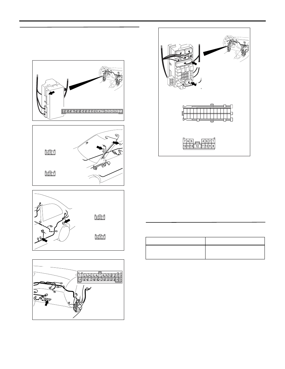
Step 5. Check the wiring harness from terminal
No.2 of the D-18 <front: LH>, D-01 <front: RH>,
D-08 <rear: RH> or D-11 <rear: LH> door switch
connector to terminal No.7 of the C-226
ETACS-ECU connector.
NOTE:
Prior to the wiring harness inspection, check interme-
diate connector C-113 <RH> and junction block con-
nector C-214 <RH> or C-217 <LH>, and repair if
necessary.
• Check the input line for open circuit.
Q: Is the check result normal?
YES :
Go to Step 6.
NO :
Repair the wiring harness between each of
the door switches and the ETACS-ECU.
Step 6. Pulse check
Check the input signals from all the door switches.
OK: The M.U.T.-II/III sounds or the voltmeter
needle fluctuates.
Q: Is the check result normal?
YES :
The trouble can be an intermittent
malfunction (Refer to GROUP 00
− How to
Cope with Intermittent Malfunction
NO :
Replace the ETACS-ECU.
AC310450
Connector: C-226
AB
Junction block side
Junction block (rear view)
<LHD>
AC310463
<LHD>
AC
Harness side
Harness side
D-01
D-08
D-01
Connectors: D-01, D-08
D-08
AC310465
Harness side
D-11
D-11
AD
Connectors: D-11, D-18
<LHD>
Harness side
D-18
D-18
AC310452
Connector: C-113
AF
<LHD>
System switch
Check condition
All of the door switches
A door is opened when
all the doors are closed
AC310449
C-214
Harness side
21
7
16 15
17
18
20 19
1
2
3
4
5
6
23 22
24
25
28
26
27
9
8
10
11
14
12
13
Connectors: C-214, C-217
AB
C-214
Junction block (front view)
<LHD>
C-217
C-217
Harness side