Mitsubishi Lancer Evolution IX. Manual - part 172
INPUT SIGNAL PROCEDURES
SMART WIRING SYSTEM (SWS) NOT USING SWS MONITOR
54B-251
DIAGNOSTIC PROCEDURE
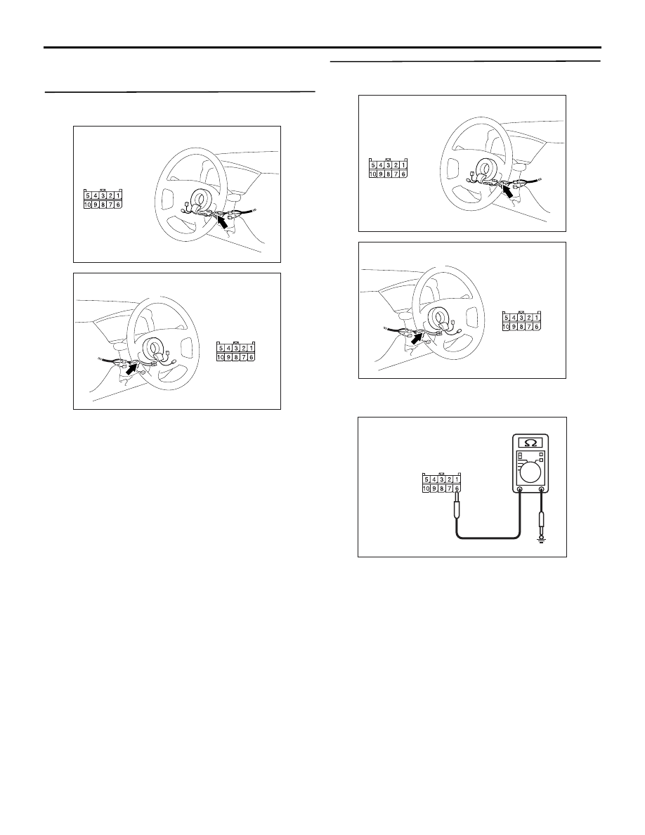
Step 1. Connector check: C-206 column switch
connector
Q: Is the check result normal?
YES :
Go to Step 2.
NO :
Repair the defective connector.
Step 2. Resistance measurement at the C-206
column switch connector
(1) Disconnect the connector, and measure at the
column switch side.
(2) Resistance between C-206 column switch
connector terminal No.6 and body earth
OK: The resistance should rise from 0 to
1 k
Ω when the windshield intermittent
wiper volume is rotated from "Fast" to
"Slow".
Q: Is the check result normal?
YES :
Go to Step 3.
NO :
Replace the column switch.
AC310479
AB
Connector: C-206
<LHD>
Harness side
AC310481AB
Harness side
Connector: C-206
<RHD>
AC310479
AB
Connector: C-206
<LHD>
Harness side
AC310481AB
Harness side
Connector: C-206
<RHD>
AC301541GV
Connector C-206
(Harness side)