Mitsubishi Lancer Evolution IX. Manual - part 115
DIAGNOSTIC TROUBLE CODE PROCEDURES
SMART WIRING SYSTEM (SWS) NOT USING SWS MONITOR
54B-23
DIAGNOSIS CODE SET CONDITIONS
If the front-ECU has sent abnormal signal to the
ETACS-ECU for consecutively 15 communication
cycles (0.6 second), the diagnosis code will be set. If
the front-ECU has sent normal signal to the
ETACS-ECU for consecutively 15 communication
cycles (0.6 second), the ETACS-ECU will stop send-
ing the diagnosis code.
POSSIBLE CAUSES
• Malfunction of the front-ECU
• Malfunction of the ETACS-ECU
• Damaged harness wires and connectors
DIAGNOSTIC PROCEDURE
Step 1. M.U.T.-II/III diagnosis code.
(1) Ignition switch: ON
(2) On completion, check that diagnosis code No.13
is not reset.
Q: Is diagnosis code No.13 set?
YES :
Go to Step 5.
NO :
Go to Step 2.
Step 2. Connector check: A-10X front-ECU
connector
Q: Is the check result normal?
YES :
Go to Step 3.
NO :
Repair the defective connector.
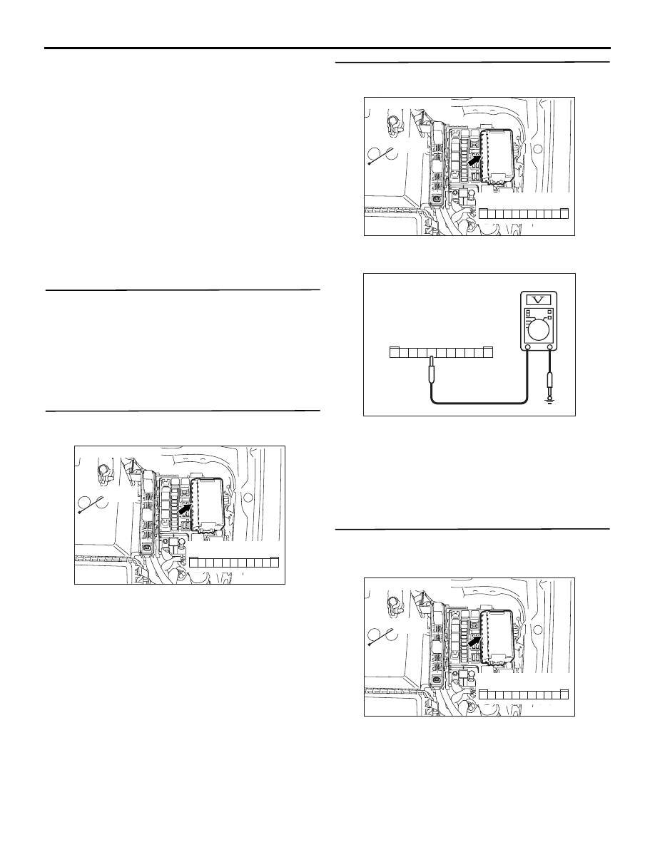
Step 3. Voltage measurement at A-10X front-ECU
connector
(1) Remove the front-ECU, and measure at the relay
box side.
(2) Voltage between A-10X front-ECU connector
terminal No.7 and body earth
OK: System voltage
Q: Is the check result normal?
YES :
Replace the front-ECU.
NO :
Go to Step 4.
Step 4. Check the wiring harness between A-10X
front-ECU connector terminal No.7 and the
battery.
• Check the power supply line for open circuit.
Q: Is the check result normal?
YES :
The trouble can be an intermittent
malfunction (Refer to GROUP 00
− How to
Cope with Intermittent Malfunction
NO :
Repair the wiring harness.
AC310572AB
Connector: A-10X
Relay box side
10
11
5
9 8 7 6
4 3
1
2
Battery
AC310572AB
Connector: A-10X
Relay box side
10
11
5
9 8 7 6
4 3
1
2
Battery
AC301541CT
5
11
9
10
8 7 6
2
4 3
1
Connector A-10X
(Relay box side)
AC310572AB
Connector: A-10X
Relay box side
10
11
5
9 8 7 6
4 3
1
2
Battery