Mitsubishi Lancer Evolution 7. Manual - part 408
HEATER, AIR CONDITIONER AND VENTILATION
-
Compressor
55-39
"
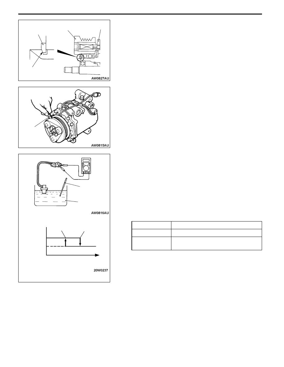
BA SNAP RING INSTALLATION
Using snap ring pliers, fit the snap ring so that the snap
ring’s tapered part is on the outside.
"
CA SELF-LOCKING NUT INSTALLATION
Using a special tool, as when removing the nut, secure the
armature and tighten the self-locking nut.
"
DA AIR GAP ADJUSTMENT
Apply voltage from the battery to the magnetic clutch and
check that the clutch air gap is inside the type. value.
If outside the type. value, use a shim to adjust the gap.
Standard value: 0.3 – 0.5 mm
NOTE
The shims are available in 0.05 mm steps across the thickness
range 0.35 - 0.70 mm, and in 0.1 mm steps of thickness.
INSPECTION
Cooling temperature switch
1. Dip the metal part of the cooling temperature switch into
engine oil and increase the oil temperature using a gas
burner or similar.
Caution
Do not heat more than necessary.
2. When the oil temperature reaches the type. value, check
that voltage is supplied between the terminals.
Standard value:
Item
Temperature
Continuity
Slightly below 150°C
No continuity
150°C or higher
(until temperature falls to 120°C when OFF)
Snap ring
Rotor
Field core
Tapered part
Thickness
gauge
Thermometer
Engine oil
Continuity
No continuity
Oil temperature
120°C
150°C