Mitsubishi Lancer Evolution 7. Manual - part 364
SRS -
Troubleshooting
52B-21
OK
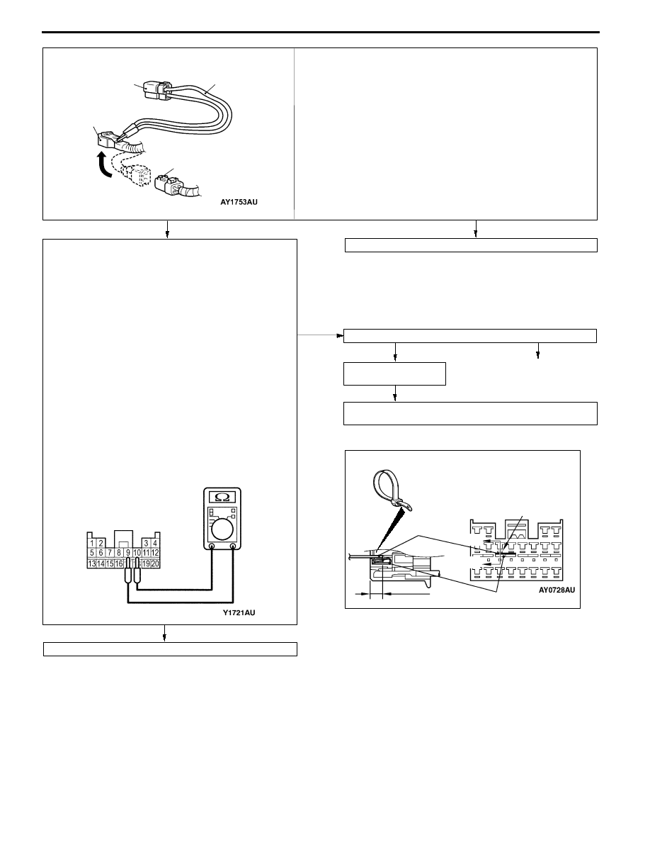
<Check the circuit between the SRS-ECU and the front
passenger’s air bag module>
Measure at the C-21 SRS-ECU connector.
D
Disconnect the SRS-ECU connector C-21.
D
Disconnect the front passenger’s air bag module connector
C-109.
Caution
Disconnect the connector and short-circuit the squib
circuit before releasing the short bar of the SRS-ECU
connector in the following operation.
D
Cable bands between terminals 9, 10 and the short bar
(width:3 mm, thickness:0.5 mm) between terminals 11 and
12 and the short bar, and release the short bar.
(See Figure A.)
Caution
As the short bar may not be releasable if inserted
insufficiently, insert more than 4 mm.
D
Measure at the harness side
D
Continuity check between terminals 9 and 10
Caution
Do not directly insert a probe or other devices at the
front of the connector to avoid a possible decrease in
the contact pressure.
OK: No continuity
YES
NO
Replace the front passenger’s seat air bag module (squib).
Resistor harness
(MB991866)
Dummy resistor
(MB991865)
resistance (3Ω)
Instrumental panel
wiring harness
Front passenger’s air bag
module connector
<Check the front passenger’s air bag module (squib)>
MUT-II self-diag code
D
Connect the dummy resistor (MB991865) to the resistor harness
(MB991866).
D
Disconnect the front passenger’s air bag module connector C-109
and insert the resistor harness (MB991866) behind the harness side
connector.
Caution
Do not directly insert a probe or other devices at the front of the
connector to avoid a possible decrease in the contact pressure.
D
Connect the negative (-) terminal of the battery
D
Check the diagnosis code again after erasing the memory.
Is code No.24 output?
Check the trouble
symptoms.
NG
Check the harness between the front passenger’s air bag
module and the SRS-ECU, and repair if necessary.
NG
YES
NG
Correct
Check connector: C-21, C-109
Connector C-21
Figure A
Terminal
Short bar
Front view of C-21
SRS-ECU connector
(harness side).
Cable band
and etc.
Section
A - A
4 mm or more
A
A
Replace the SRS-ECU.