Mitsubishi Lancer Evolution 7. Manual - part 285
REAR AXLE -
Rear Hub Assembly
27B-25
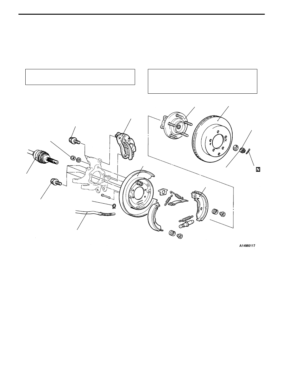
REAR HUB ASSEMBLY
REMOVAL AND INSTALLATION
Caution
If the vehicle is equipped with the Brembo disc brake, during maintenance, take care not to contact
the parts or tools to the caliper because the paint of caliper will be scratched. And if there is
brake fluid on the caliper, wipe out quickly.
Pre-removal Operation
Gear Oil Draining (Refer to P. 27B-17.)
Post-installation Operation
D
Gear Oil Filling (Refer to P. 27B-17.)
D
Parking Brake Lever Stroke Adjustment (Refer to
GROUP 36 – On-vehicle Service.)
2
118 ± 19 N·m
4
1
3
225 ± 25 N·m
8
7
6
5
10
9
54 ± 5 N·m
81 ± 6 N·m
Removal steps
A
A"
1. Rear brake caliper
2. Rear brake disc
3. Parking brake shoe & lining assembly
(Refer to GROUP 36 - Parking Brake
Drum.)
4. Clip
5. Parking brake cable connection
6. Split pin
A
B" "AA 7. Drive shaft nut
8. Rear drive shaft assembly
A
C"
9. Rear hub assembly
10. Backing plate