Mitsubishi Lancer Evolution 7. Manual - part 276
FRONT AXLE -
Hub and Knuckle Assembly
26-7
REMOVAL SERVICE POINTS
A
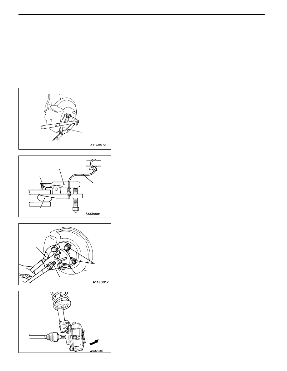
A" CALIPER ASSEMBLY REMOVAL
Secure the removed caliper assembly with wire, etc.
Caution
If the vehicle is equipped with the Brembo disc brake,
during maintenance, take care not to contact the parts
or tools to the caliper because the paint of caliper will
be scratched. And if there is brake fluid on the caliper,
wipe out quickly.
A
B" CASTLE NUT REMOVAL
Caution
Do not apply the vehicle weight to the wheel bearing
while loosening the castle nut. Otherwise wheel bearing
will be damaged.
A
C" TIE ROD END DISCONNECTION
Caution
1. Loosen the nut only; do not remove it from the ball
joint. Otherwise ball joint thread will be damaged.
2. The special tool should be suspended by a cord to
prevent it from coming off.
A
D" DRIVE SHAFT REMOVAL
1. Use the special tools to push out the drive shaft from
the hub.
2. Withdraw the drive shaft from the hub by pulling the bottom
of the brake disc towards you, and then remove the hub
retaining bolts.
MB990767
Nut
Cord
Ball joint
MB991113
or
MB990635
MB990242
MB990767
MB991354
MB990244
(Three)