Mitsubishi Lancer Evolution 7. Manual - part 241


  Index      Mitsubishi     Mitsubishi Lancer Evolution 7 - service repair manual


Search            


Content   ..  239  240  241  242   ..


Mitsubishi Lancer Evolution 7. Manual - part 241


CLUTCH -

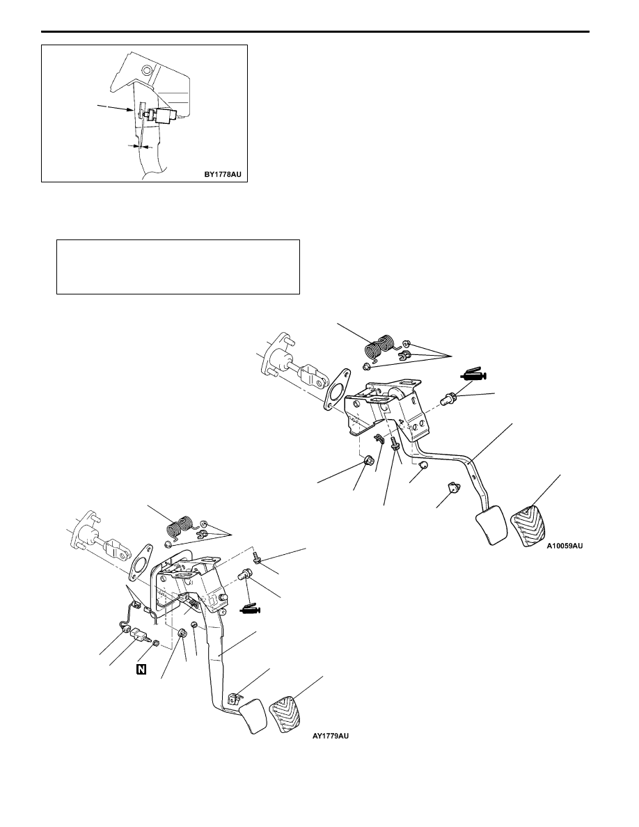
On-Vehicle Service/Clutch Pedal

21A-5

5. Fix the clutch pedal position switch by rotating approx.

quarter turn to clockwise in the position as shown in the

illustration.

6. Connect the connector to the clutch pedal position switch.

7. Check that the engine starts when the clutch is released.

CLUTCH PEDAL

REMOVAL AND INSTALLATION

Post-installation Operation
D

Clutch Pedal Adjustment (Refer to P.21A-2.)

D

Clutch Pedal Position Switch Adjustment (Refer to

P.21A-4.)

6

7

13 ± 2 N·m

<L.H. drive vehicles>

<R.H. drive vehicles>

1

12 ± 2 N·m

8

11

2

4

5

9

12 ± 2 N·m

6

7

13 ± 2 N·m

10

8

12

13

3

14

5

9

10

11

12

13

14

Full stroke

position of

clutch pedal

Approx.

3.5 mm

CLUTCH -

Clutch Pedal

21A-6

Removal steps
D

Column cover, under cover, lower

frame (Refer to GROUP 52A.)

1. Connector connection

2. Clutch pedal position switch

3. Clutch pedal position switch sub-har-

ness

4. Clip

5. Stopper

6. Snap pin

7. Clevis pin

8. Clutch master cylinder mounting nut

9. Master cylinder member mounting bolt

10. Pedal pad

11. Pedal stopper

12. Clutch pedal assembly

13. Turn over spring

14. Bushing

INSPECTION

CLUTCH PEDAL POSITION SWITCH CONTINUITY
CHECK
1. Connect the circuit tester (Ω range) to the connector of

clutch pedal position switch.

2. When the shaft is pushed more than the dimension as

shown in the illustration if there is not continuity, and

removing if there is continuity, the switch is good condition.

Continuity

2.5 ± 1 mm

No continuity

CLUTCH -

Clutch Control

21A-7

CLUTCH CONTROL

REMOVAL AND INSTALLATION

Pre-removal Operation

Clutch Fluid Draining

Post-installation Operation
D

Clutch Fluid Supplying

D

Clutch Pedal Adjustment (Refer to P.21A-3.)

D

Clutch Pedal Position Switch Adjustment (Refer to

P.21A-4.)

D

Clutch Line Bleeding (Refer to P.21A-4.)

<L.H. drive vehicles>

7

6

11

4

9

5

2

1

3

10

15 ± 1 N·m

30 ± 4 N·m

13 ± 2 N·m

12 ± 2 N·m

18 ± 3 N·m

10

8

Specified grease:
MITSUBISHI genuine grease
Part No. 0101011

Release cylinder

push rod

Release fork

11

Clutch master cylinder removal

steps

1. Clevis pin assembly

2. Eye bolt

3. Gasket

4. Reservoir hose

5. Clevis pin and pushrod assembly con-

necting part

6. Clutch master cylinder

7. Sealer

8. Retainer assembly

Clutch release cylinder removal

steps

10. Clutch pipe

11. Clutch release cylinder

Clutch line removal steps

9. Clutch hose

10. Clutch pipe

CLUTCH -

Clutch Control

21A-8

<R.H. drive vehicles>

1

2

3

4

5

9

7

8

6

15 ± 1 N·m

13 ± 2 N·m

18 ± 3 N·m

6, 8

Specified grease:
MITSUBISHI genuine grease
Part No. 0101011

Release cylinder

push rod

Release fork

7

Clutch master cylinder removal

steps

1. Clevis pin assembly

2. Clutch pipe connection

3. Reservoir hose

4. Clutch master cylinder

5. Sealer

Clutch release cylinder removal

steps

6. Clutch pipe

7. Clutch release cylinder

Clutch line removal steps

8. Clutch pipe

9. Clutch hose


Content   ..  239  240  241  242   ..