Mitsubishi Lancer Evolution 7. Manual - part 14
POWER TRAIN - Manual Transmission
2-9
POWER TRAIN
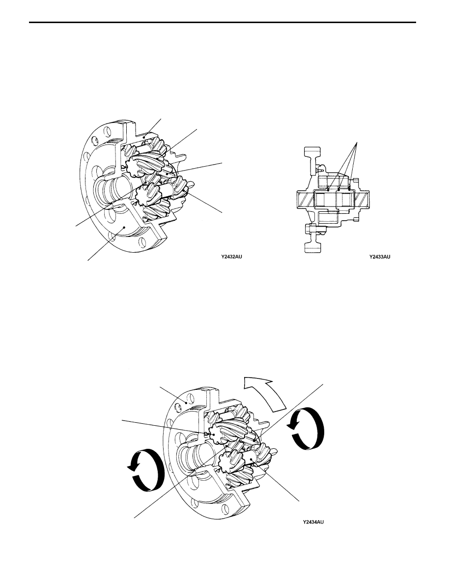
Helical Gear LSD
The helical gear LSD is composed of four long pinions, four short pinions, three thrust washers, side
gears A and B, and cases A and B.
The long pinions are in contact with the side gear B and short pinions, while the short pinions are in
contact with the side gear A and long pinions.
Case B
Case A
Side gear B
Side gear A
Long pinion
Short pinion
Thrust washer
Power Flow
Operations in forward driving
During forward driving, as the differential case and and drive shaft rotate at the same speed, they
rotate at the assembly without the inside of the differential moving.
The driving force at this time will be transmitted as follows.
Differential case
→
Long and short pinions
→
Side gears A and B
→
Drive shaft
Side gear B
Side gear A
Long pinion
Short pinion
Differential case
Driving power