Mitsubishi Lancer Evolution VI. Manual - part 119


  Index      Mitsubishi     Mitsubishi Lancer Evolution VI - service repair manual


Search            


Content   ..  117  118  119  120   ..


Mitsubishi Lancer Evolution VI. Manual - part 119


  – Condenser and Condenser Fan

HEATER AND MANUAL
AIR CONDITIONER

55-28

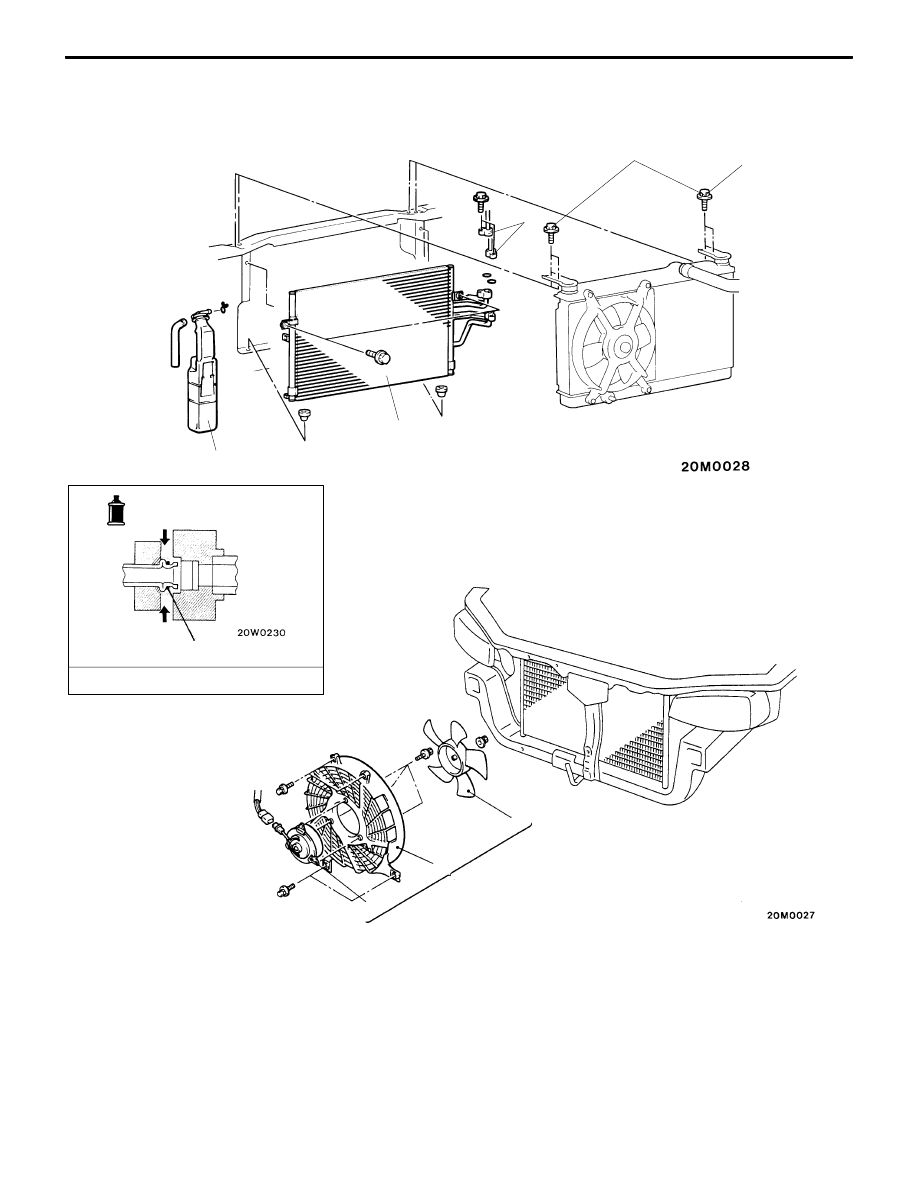
CONDENSER AND CONDENSER FAN

REMOVAL AND INSTALLATION

 12 Nm

4

6

2

1

5

3

7

8

Piping connection

O-ring

A/C Compressor oil: SUN PAG 56

Condenser fan removal steps

D

Front bumper

A

A

"

1. Condenser fan motor and shroud

assembly

2. Fan
3. Motor assembly
4. Shroud

Condenser removal steps

D

Discharging and charging of 
refrigerant (Refer to P.55-6.)

5. Reserve tank
6. Radiator mounting bolt

A

B

"

7. Discharge hose, liquid pipe A 

connection

A

C

"

8. Condenser

  – Condenser and Condenser Fan

HEATER AND MANUAL
AIR CONDITIONER

55-29

REMOVAL SERVICE POINTS

A

A

"

FAN MOTOR AND SHROUD ASSEMBLY
REMOVAL

Remove the clamp bolt of the power steering oil cooler pipe.
Remove the fan motor and shroud assembly while pulling
the power steering oil cooler pipe toward you.

A

B

"

DISCHARGE HOSE / LIQUID PIPE A
DISCONNECTION

Plug the open end of the disconnected hose and the opening
in the cooling unit not to let foreign matter get into them.

Caution
Seal the hoses completely, otherwise the compressor
oil and receiver will absorb water vapour easily.

A

C

"

CONDENSER REMOVAL

Move the radiator to the engine side and then lift up the
condenser to remove it.

INSPECTION

CONDENSER FAN MOTOR CHECK

Battery connection terminal

Condenser fan operation

1

2

Rotate

Condenser

  – Refrigerant Line

HEATER AND MANUAL
AIR CONDITIONER

55-30

REFRIGERANT LINE

REMOVAL AND INSTALLATION

Pre-removal and Post-installation Operation

D

Discharging and Charging of Refrigerant 
(Refer to P.55-6.)

D

Air Cleaner Case and Hose Removal and
Installation

O-ring

Piping connection

A/C Compressor oil: SUN PAG 56

4

6

2

1

5

3

7

8

9

10

3

A

A

"

1. Liquid pipe B
2. Clip
3. Clamp

A

A

"

4. Suction hose assembly

A

A

"

5. Liquid pipe A

6. Clip

A

A

"

7. Receiver
8. Dual pressure switch
9. Receiver bracket

A

A

"

10. Discharge hose

A

A

"

HOSE / PIPE DISCONNECTION

Plug the open end of the disconnected hose and the opening
in the cooling unit not to let foreign matter get into them.

Caution
Seal the hoses completely, otherwise the compressor
oil and receiver will absorb water vapour easily.

  – Ducts

HEATER AND MANUAL
AIR CONDITIONER

55-31

DUCTS

REMOVAL AND INSTALLATION

<Standard model>

<Vehicles for cold regions>

4

6

2

1

5

3

7

8

8

1. Center air outlet assembly
2. Center ventilation duct 

(Refer to P.55-18, 19.)

3. Undercover 

<Vehicles for cold regions> 
(Refer to P.55-20.)

4. Side air outlet assembly
5. Defroster nozzel
6. Distribution duct

Rear heater duct removal steps

D

Front seat assembly

D

Floor console assembly

7. Rear heater duct <Vehicles for cold

regions>

D

Radio and tape player

8. Foot duct


Content   ..  117  118  119  120   ..