Mitsubishi Lancer Evolution VI. Manual - part 49


  Index      Mitsubishi     Mitsubishi Lancer Evolution VI - service repair manual


Search            


Content   ..  47  48  49  50   ..


Mitsubishi Lancer Evolution VI. Manual - part 49


CLUTCH  – 

Clutch Pedal

21A-4

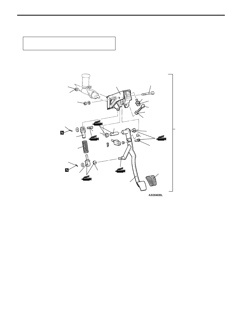
CLUTCH PEDAL <L.H. DRIVE VEHICLES>

REMOVAL AND INSTALLATION

Post-installation Operation
Clutch Pedal Adjustment (Refer to P. 21A-2.)

13 Nm

1

14

13

12

2

8

18

9

11

3

10

13 Nm

29 Nm

19

6

4

7

12 Nm

5

5

17

15

16

12

Removal steps

1. Clutch master cylinder installation

nut

2. Master cylinder member bracket

installation bolt

3. Clevis pin
4. Pedal support member and clutch

pedal assembly

5. Split pin
6. Clevis pin
7. Bushing
8. Rod A

9. Rod B

10. Turn over spring

11. Bolt

12. Bushing
13. Pipe
14. Clutch pedal
15. Pedal pad
16. Stopper
17. Adjusting bolt
18. Locking nut
19. Pedal support member

CLUTCH  – 

Clutch Control

21A-5

CLUTCH CONTROL <L.H. DRIVE VEHICLES>

REMOVAL AND INSTALLATION

Pre-removal Operation

D

Clutch Fluid Draining

D

Air Cleaner Removal

Post-installation Operation

D

Air Cleaner Installation

D

Clutch Fluid Supplying

D

Clutch Line Bleeding (Refer to P.21A-3.)

D

Clutch Pedal Adjustment (Refer to P. 21A-2.)

15 Nm

Specified grease:
MITSUBISHI genuine grease
Part No. 0101011

5

6

8

7

6

1

4

13 Nm

15 Nm

15 Nm

19 Nm

5

15 Nm

3

2

7

Release
fork

Clutch master cylinder removal
steps

1. Clevis pin
2. Clutch pipe connection
3. Clutch master cylinder

Clutch release cylinder removal
steps

4. Clutch pipe connection
5. Clutch release cylinder

Clutch line removal steps

6. Clutch pipe
7. Hose clip
8. Clutch hose

CLUTCH  – 

Clutch Control

21A-6

DISASSEMBLY AND REASSEMBLY

CLUTCH MASTER CYLINDER

13 Nm

6

7

3

1

2

Piston repair kit

Clutch fluid:
Brake fluid DOT3 or DOT4

Grease: Rubber grease

2

5

4

4

1

3

4

4

8

Disassembly steps

1. Piston stopper ring

"

A

A

2. Push rod assembly
3. Boot
4. Piston assembly
5. Reservoir cap
6. Spring pin
7. Reservoir tank
8. Clutch master cylinder body

Caution
Do not disassemble piston assembly.

INSTALLATION SERVICE POINT

A

A

"

PUSH ROD ASSEMBLY INSTALLATION

Set the length of the push rod assembly to the shown
dimension to make the adjustment of the clutch pedal easier.

122.5 mm


Content   ..  47  48  49  50   ..