Mitsubishi Lancer Evolution VI. Manual - part 25
ENGINE –
Turbocharger
11-75
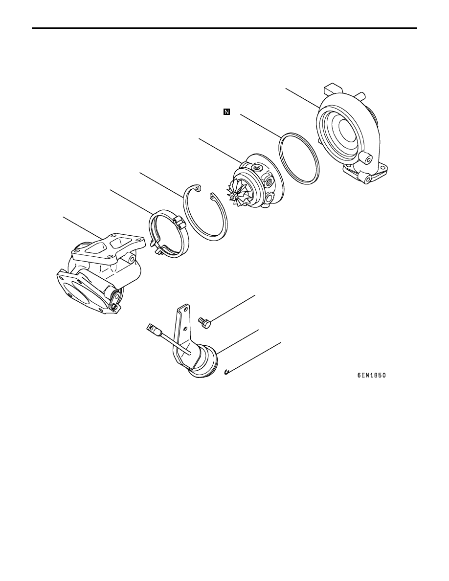
TURBOCHARGER
DISASSEMBLY AND REASSEMBLY
1
2
3
4
5
6
7
8
11 Nm
Disassembly steps
"
F
A D
Inspection of turbocharger waste gate
actuator operation
1. Snap pin
2. Waste gate actuator
"
E
A
3. Coupling
"
D
A
4. Turbine housing
A
A
" "
C
A
5. Snap ring
A
B
" "
B
A
6. Turbine wheel assembly
7. Compressor cover
"
A
A
8. O-ring