Mitsubishi Lancer Evolution VI. Manual - part 12


  Index      Mitsubishi     Mitsubishi Lancer Evolution VI - service repair manual


Search            


Content   ..  10  11  12  13   ..


Mitsubishi Lancer Evolution VI. Manual - part 12


ENGINE  – 

Timing Belt

11-23

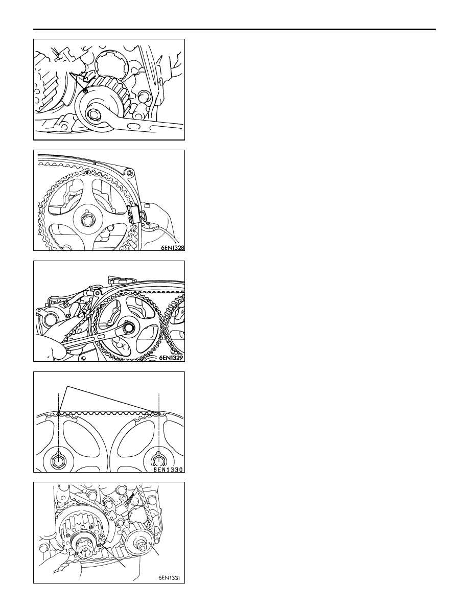
(6) Remove the Phillips screwdriver. Place the oil pump

sprocket in a position where its timing mark is one tooth
offset from the mated timing mark in the counterclockwise
direction.

(7) Fit the timing belt over the exhaust side camshaft sprocket,

and secure it at the illustrated position using a paper
clip.

(8) Turn the intake side camshaft sprocket as shown to a

position where its timing mark is one tooth offset from
the mated timing mark in the counterclockwise direction.
Then, fit the timing belt over the sprocket and secure
it with a paper clip.

NOTE
The intake camshaft will be turned a little clockwise by
the valve spring tension and stabilized in position even
if the belt is clipped at one tooth offset position.

(9) Check to ensure that the timing marks on the intake

camshaft sprocket side are in alignment when the exhaust
camshaft sprocket is turned clockwise to align the timing
marks.

NOTE
The timing belt span between the intake and exhaust
sprockets will have 17 cogs.

(10)Fit the timing belt over the idler pulley, oil pump sprocket

and crankshaft sprocket in this order.

NOTE
Be careful that the belt does not become slack.

Timing mark

6EN1327

Timing mark

Crankshaft
sprocket

Oil pump
sprocket

ENGINE  – 

Timing Belt

11-24

(11) Fit the timing belt over the tensioner pulley.

NOTE
When fitting the timing belt over the tensioner pulley,
turn the intake side camshaft sprocket a little
counterclockwise, as this will facilitate the work.

(12)Turn the crankshaft pulley a little in the illustrated direction

to pull up the timing belt at the idler pulley side.

(13)Check to ensure that the timing marks on the crankshaft

sprocket, oil pump sprocket and exhaust camshaft
sprocket are all offset one tooth from the corresponding
timing marks in the counterclockwise direction.

(14)Using the special tool, turn the tensioner pulley in the

illustrated direction to strain the timing belt. Then, secure
the tensioner temporarily by tightening the retaining bolt
lightly.

NOTE
There must be no slack in the timing belt between the
intake and exhaust camshafts.

(15)Turn the crankshaft to align the timing mark with the mark

for No. 1 cylinder top dead center in the compression
stroke.

(16)Set the special tool as shown and screw it in up to the

position where the wire inserted in the auto-tensioner
when installing it can be moved lightly.

Crankshaft
sprocket

MD998767

MD998738

ENGINE  – 

Timing Belt

11-25

(17)Loosen the retaining bolt of the tensioner pulley.

Caution
Loosening the retaining bolt can cause the intake
and exhaust camshafts to turn, resulting in slackened
timing belt. Use care that the timing belt does not
come off the sprockets at this time.

(18)Pull up the slack of the timing belt by turning the tensioner

in illustrated direction using the special tool and a torque
wrench (0 – 5 Nm).

(19)From this position, turn back the tensioner until the torque

wrench reading becomes 3.5 Nm, then secure it by
tightening the retaining bolt.

(20)Remove the special tool attached in step (16).
(21)Rotate the crankshaft clockwise 2 turns. Then, leave it

intact 15 minutes.

(22)Check to see that the wire inserted when installing the

auto-tensioner can be pulled out lightly. If it can be pulled
out lightly, the timing belt is being tensioned properly.
If so, remove the wire. In addition, check that the rod
protrusion from the auto-tensioner meets the standard
value, which is also an indication of properly tensioned
timing belt.

Standard value: 3.8 – 4.5 mm

(23)If the wire cannot be removed with a light force, repeat

steps (16) through (21) until the proper belt tensioner
is obtained.

INSPECTION

TIMING BELT

Replace belt if any of the following conditions exist.

(1) Hardening of back rubber.

Back side is glossy without resilience and leaves no indent
when pressed with fingernail.

(2) Cracks on rubber back.
(3) Cracks or peeling of canvas.
(4) Cracks on rib root.
(5) Cracks on belt sides.

MD998767

ENGINE  – 

Timing Belt

11-26

(6) Abnormal wear of belt sides. The sides are normal if

they are sharp as if cut by a knife.

(7) Abnormal wear on teeth.
(8) Missing tooth.

AUTO TENSIONER

(1) Check the auto tensioner for possible leaks and replace

as necessary.

(2) Check the rod end for wear or damage and replace as

necessary.

(3) Measure the rod protrusion. If it is out of specification,

replace the auto tensioner.

Standard value: 12 mm

(4) Press the rod with a force of 98 to 196 N and measure

its protrusion.

(5) If the measured value is 1 mm or more shorter than the

value obtained in step (3), replace the auto tensioner.

12 mm

98 to 196 N

Movement


Content   ..  10  11  12  13   ..