Mitsubishi Lancer Evolution VI. Manual - part 3


  Index      Mitsubishi     Mitsubishi Lancer Evolution VI - service repair manual


Search            


Content   ..  1  2  3  4  ..


Mitsubishi Lancer Evolution VI. Manual - part 3


GENERAL  – 

How to Use Troubleshooting/Inspection Service Points

00-9

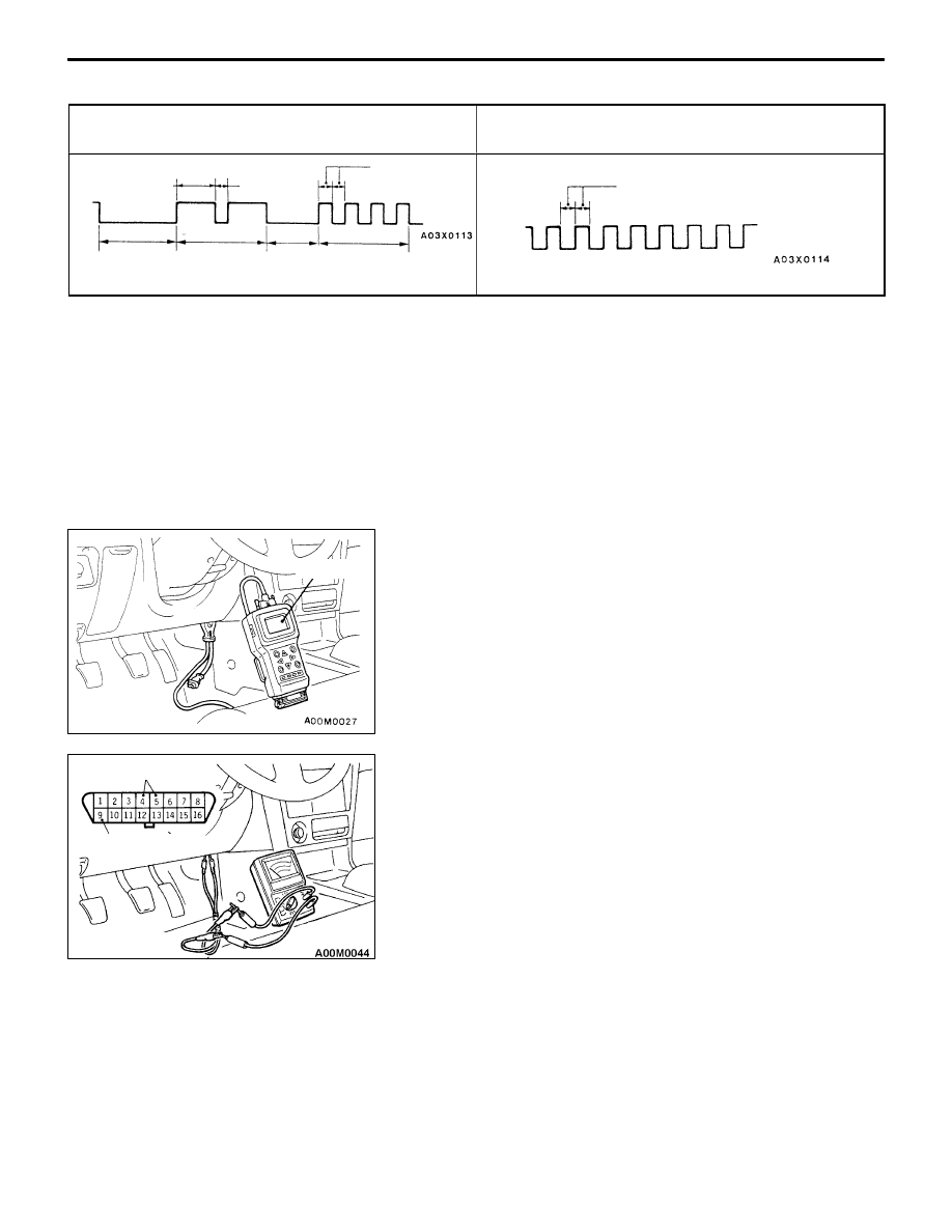
Diagnosis result display method when using a voltmeter

Example of diagnosis code voltage wave pattern for
diagnosis code No. 24

Normal voltage wave pattern

12V
0 V

1.5 secs.

0.5 sec.

0.5 sec.

Pause
time 3
secs.

Tens
signal

Place
division
2 secs.

Units
signal

12 V

0 V

0.5 sec.

METHOD OF ERASING DIAGNOSIS CODES

WHEN USING THE MUT-

II

Connect the MUT-

II 

to the diagnosis connector and erase the diagnosis code.

Caution
Turn off the ignition switch before connecting or disconnecting the MUT-

II

.

WHEN NOT USING THE MUT-

II

(1) Turn the ignition switch to OFF.
(2) After disconnecting the battery cable from the battery (–) terminal for 10 seconds or more, reconnect

the cable.

(3) After the engine has warmed up, run it at idle for about 15 minutes.

INPUT SIGNAL INSPECTION POINTS <VEHICLES
WITH ETACS-ECU>

WHEN USING THE MUT-

II

1.

Connect the MUT-

II

 to the diagnosis connector.

Caution
The MUT-

II

  should be connected or disconnected after

turning the ignition switch to the OFF position.

2.

If buzzer of the MUT-

II

 sounds once when the each switch

is operated (ON/OFF), the ETACS-ECU input signal for
that switch circuit system is normal.

WHEN USING VOLTMETER

1.

Use the special  tool to connect a voltmeter between
the earth terminal (No. 4 or 5) and the ETACS terminal
(No. 9) of the diagnosis connector.

2.

If the voltmeter indicator deflects once when the each
switch is operated (ON/OFF), the ETACS-ECU input signal
for that switch circuit system is normal.

MUT-

II

Earth terminal

ETACS  terminal

MB991529

GENERAL  – 

How to Use Troubleshooting/Inspection Service Points

00-10

HOW TO USE THE INSPECTION PROCEDURES

The causes of a high frequency of problems occurring in electronic circuitry are generally the connectors,
components, the ECU and the harnesses between connectors, in that order. These inspection procedures
follow this order, and they first try to discover a problem with a connector or a defective component.

D

Indicator does not turn on or off even if control
mode switch is pressed.

D

Indicator switch should not be illuminated is
illuminated.

Probable cause

OK

OK

OK

Measure at switch connector A-44

D

Disconnect the connector, and measure at the harness
side.

D

Voltage between terminal 6 – earth and terminal 8 –
earth
OK: Approx. 5V

OK

NG

Check the following connector. A-44

Repair

OK

Check trouble symptom.

Replace the ECS-ECU.

In the above cases, the ECS switch circuit is defective or the indicator
circuit is defective.

CHECKING PROCEDURE 4

2.

Indicates inspection carried out using the
MUT-

II

.

Indicates the operation and inspection proce-
dures.
Indicates the OK judgement conditions.

3.

Detailed inspection procedures (methods)
such as component inspection and circuit
inspection are listed on a separate page, and
are given here for reference.

5.

Inspect the contact condition at each connector terminal.
(Refer to Connector Inspection Service Points.)
The connector position can be located in the wiring diagram in the
electrical wiring manual by means of this symbol.
Caution
After carrying out connector inspection, always be sure to
reconnect the connector as it was before.

6.

Confirm that there are trouble symptoms. If trouble symptoms have
disappeared, the connector may have been inserted incorrectly and the
trouble symptom may have disappeared during inspection.
If it seems that trouble symptoms still remain, proceed to the next page of
instructions.

7.

If trouble symptoms still remain up to this stage, there is a possibility that there is an
open or short circuit in the harness between the connectors, so check the harness.
Alternatively, the cause may be a defective ECU, so try replacing the ECU and check
if the trouble symptom disappears.

NG

ECU switch component inspection (Refer to P.3-44.)

NG

1.

Comments on the diagnosis code or trouble
symptom above.

MUT-

II

 Data list

17 Control mode selection switch

OK: Voltage changes between approx. 0V 

 approx.

2.5V 

 approx. 5V when the switch is operated.

4.

Indicates voltage and resistance to be measured at a particular
connector.
(Refer to Connector Measurement Service Points.)
The connector position can be located in the wiring diagram in the
electrical wiring manual by means of this symbol.
Indicates operation and inspection procedures, inspection terminals
and inspection conditions.
Indicates the OK judgement conditions.

HARNESS INSPECTION

Check for an open or short circuit in the harness between the terminals which were defective according
to the connector measurements. Carry out this inspection while referring to the electrical wiring manual.
Here,  “Check harness between power supply and terminal xx” also includes checking for blown fuses.
For inspection service points when there is a blown fuse, refer to “Inspection Service Points for a Blown
Fuse.”

MEASURES TO TAKE AFTER REPLACING THE ECU

If the trouble symptoms have not disappeared even after replacing the ECU, repeat the inspection procedure
from the beginning.

GENERAL  – 

How to Use Troubleshooting/Inspection Service Points

00-11

CONNECTOR MEASUREMENT SERVICE POINTS

Turn the ignition switch to OFF when connecting disconnecting
the connectors, and turn the ignition switch to ON when
measuring if there are no instructions to be contrary.

IF INSPECTING WITH THE CONNECTOR CONNECTED
(WITH CIRCUIT IN A CONDITION OF CONTINUITY)

Waterproof Connectors

Be sure to use the special tool (harness connector). Never
insert a test bar from the harness side, because to do so
will reduce the waterproof performance and result in corrosion.

Ordinary (non-waterproof) Connectors

Check by inserting the test bar from the harness side. Note
that if the connector (control unit, etc.) is too small to permit
insertion of the test bar, it should not be forced; use a special
tool (the extra-thin probe in the harness set for checking
for this purpose.

IF INSPECTING WITH THE CONNECTOR DISCONNECTED

<When Inspecting a Female Pin>

Use the special tool (inspection harness for connector pin
contact pressure in the harness set for inspection).
The inspection harness for connector pin contact pressure
should be used. the test bar should never be forcibly inserted,
as it may cause a defective contact.

<When Inspecting a Male Pin>

Touch the pin directly with the test bar.

Caution
At this time, be careful not to short the connector pins
with the test bars. To do so may damage the circuits
inside the ECU.

Harness connector

Extra-thin probe

Test bar

Connector

Inspection harness
for connector pin
contact pressure

GENERAL  – 

How to Use Troubleshooting/Inspection Service Points

00-12

CONNECTOR INSPECTION

VISUAL INSPECTION

D

Connector is disconnected or improperly connected

D

Connector pins are pulled out

D

Due to harness tension at terminal section

D

Low contact pressure between male and female terminals

D

Low connection pressure due to rusted terminals or foreign
matter lodged in terminals

CONNECTOR PIN INSPECTION

If the connector pin stopper is damaged, the terminal
connections (male and female pins) will not be perfect even
if the connector body is connected, and the pins may pull
out of the reverse side of the connector. Therefore, gently
pull the harnesses one by one to make sure that no pins
pull out of the connector.

CONNECTOR ENGAGEMENT INSPECTION

Use the special tool (connector pin connection pressure
inspection harness of the inspection harness set) to inspect
the engagement of the male pins and females pins. (Pin
drawing force : 1 N or more)

Connector disconnected or improperly
connected

Defective connector contact

Harness wire breakage
at terminal section

Low contact pressure

MB991219


Content   ..  1  2  3  4  ..