Mitsubishi Grandis. Manual - part 921
TROUBLESHOOTING
TRACTION CONTROL/ACTIVE STABILITY CONTROL SYSTEM
35C-9
DIAGNOSTIC TROUBLE CODE
PROCEDURES <TCL/ASC-ECU>
Code No.C1200: Front Right Wheel Speed Sensor (Open Circuit or Short Circuit)
Code No.C1205: Front Left wheel Speed Sensor (Open Circuit or Short Circuit)
Code No.C1210: Rear Right wheel Speed Sensor (Open Circuit or Short Circuit)
Code No.C1215: Rear Left wheel Speed Sensor (Open Circuit or Short Circuit)
CAUTION
If there is any problem in the CAN bus lines, an
incorrect diagnosis code may be set. Diagnose
the CAN bus lines before the diagnosis codes
(Refer to GROUP 54D, CAN bus-line diagnostic
flow
OPERATION
• Wheel speed sensor is a kind of a pulse
alternator. It consists of encoders (a plate on
which north and south pole sides of the magnets
are arranged alternately) for detecting wheel
speed which rotates at the same speed of the
wheels and speed sensors. This sensor outputs
frequency pulse signals in proportion to wheel
speed.
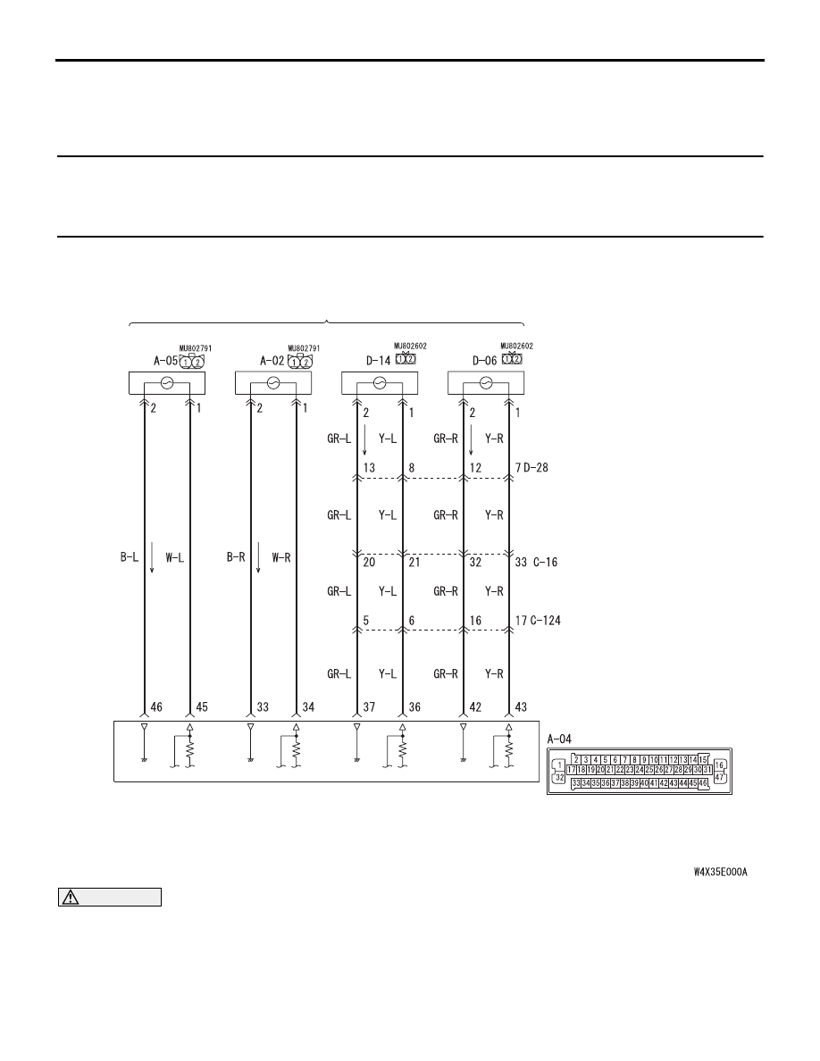
(FRONT: LH)
(FRONT: RH)
(REAR: LH)
(REAR: RH)
WHEEL SPEED SENSOR
TCL/ASC-ECU
Wire colour code
B : Black LG : Light green G : Green L : Blue W : White Y : Yellow SB : Sky blue
BR : Brown O : Orange GR : Gray R : Red P : Pink V : Violet
Wheel Speed Sensor Circuit