Mitsubishi Grandis. Manual - part 320


  Index      Mitsubishi     Mitsubishi Grandis - service repair manual


Search            


Content   ..  318  319  320  321   ..


Mitsubishi Grandis. Manual - part 320


TROUBLESHOOTING

HEATER, AIR CONDITIONER AND VENTILATION

55-165

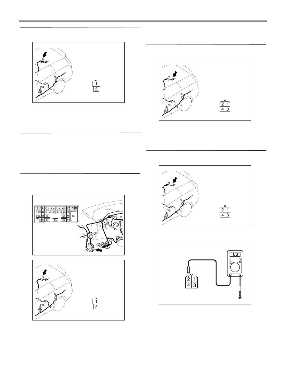
Step 11. Connector check: D-10 rear blower 
motor

Q:  Is the check result normal?

YES : 

Go to Step 12.

NO : 

Repair the connector.

Step 12. Check the rear blower motor

 Refer to 

P.55-217

.

Q: Is the check result normal?

YES : 

Go to Step 13.

NO : 

Replace the rear blower motor.

Step 13. Check the wiring harness between D-10 
rear blower motor connector terminal No.1 and 
C-15 intermediate connector terminal No.1.

• Check the rear blower relay power supply line for 

open circuit.

Q: Is the check result normal?

YES : 

Go to Step 14.

NO : 

Repair the wiring harness.

Step 14. Connector check: D-11 rear power 
transistor connector

Q: Is the check result normal?

YES : 

Go to Step 15.

NO : 

Repair the connector.

Step 15. Resistance measurement at the D-11 
rear power transistor connector.

(1) Disconnect the connector, and measure at the 

wiring harness side.

(2) Continuity between terminal 2 and body earth

OK: 2

 or less

Q: Is the check result normal?

YES : 

Go to Step 17.

NO : 

Go to Step 16.

AC310207

AD

Harness side

Connector: D-10

AC310628AE

Connector: C-15 <RHD>

AC310207

AD

Harness side

Connector: D-10

AC310207

AC

Harness side

Connector: D-11

AC310207

AC

Harness side

Connector: D-11

AC310506

Connector D-11 
(Harness side)

AT

TROUBLESHOOTING

HEATER, AIR CONDITIONER AND VENTILATION

55-166

Step 16. Check the wiring harness between D-11 
rear power transistor terminal No.2 and body 
earth.

• Check the blower linear controller earth line for 

open circuit.

Q: Is the check result normal?

YES : 

The trouble can be an intermittent 

malfunction (Refer to GROUP 00, How to 
Cope with Intermittent Malfunction 

P.00-5

).

NO : 

Repair the wiring harness.

Step 17. Connector check: C-104 A/C-ECU 
connector

Q: Is the check result normal?

YES : 

Go to Step 18.

NO : 

Repair the connector.

Step 18. Check the wiring harness between D-11 
rear power transistor connector terminal No.4 
and D-10 rear blower motor connector terminal 
No.2.

• Check the blower linear controller earth line for 

open circuit.

Q: Is the check result normal?

YES : 

Go to Step 19.

NO : 

Repair the wiring harness.

AC310207

AC

Harness side

Connector: D-11

AC310631AH

Connector: C-104 <RHD>

Harness side

51

52

53

54

55

56

57

58

59

60

61

62

63

64

65

66

67

68

69

70

71

72

AC310208

AB

Harness side

Connectors: D-10, D-11

D-10

D-11

D-10

Harness side

D-11

TROUBLESHOOTING

HEATER, AIR CONDITIONER AND VENTILATION

55-167

Step 19. Check the wiring harness between D-11 
rear power transistor connector (terminal 1 and 
3) and D-10 A/C-ECU connector (terminal 60 and 
59).

NOTE: 

Prior to the wiring harness inspection, check 
intermediate connector C-15, and repair if necessary.

• Check the blower linear controller earth line for 

open circuit.

Q: Is the check result normal?

YES : 

Go to Step 20.

NO : 

Repair the wiring harness.

Step 20. Replace the rear power transistor and 
recheck the trouble symptom

Check that the rear blower motor should work 
normally.

Q: Is the check result normal?

YES : 

This diagnosis is complete.

NO : 

Replace the A/C-ECU.

AC310208

AB

Harness side

Connectors: D-10, D-11

D-10

D-11

D-10

Harness side

D-11

AC310628AE

Connector: C-15 <RHD>

TROUBLESHOOTING

HEATER, AIR CONDITIONER AND VENTILATION

55-168

INSPECTION PROCEDURE 24: PTC heater switch system <LHD>

COMMENTS ON TROUBLE SYMPTOM

If a PTC heater switch signal is not set to the 
A/C-ECU, the PTC heater switch or the PTC heater 
switch circuit system may be defective.

POSSIBLE CAUSES

• Malfunction of the PTC heater switch

• Malfunction of the automatic air conditioner 

control panel (A/C-ECU)

DIAGNOSIS

Step 1. Connector check: C-30 PTC heater switch 
connector

Q: Is the check result normal?

IGNITION
SWITCH (IG2)

PTC
HEATER
SWITCH

A/C-ECU

Wire colour code
B : Black     LG : Light green     G : Green     L : Blue     W : White     Y : Yellow     SB : Sky blue
BR : Brown     O : Orange     GR : Gray     R : Red     P : Pink     V : Violet

PTC Heater Switch Circuit

AC310613

AM

Connector: C-30 <LHD>

Harness side


Content   ..  318  319  320  321   ..