Mitsubishi Grandis. Manual - part 299


  Index      Mitsubishi     Mitsubishi Grandis - service repair manual


Search            


Content   ..  297  298  299  300   ..


Mitsubishi Grandis. Manual - part 299


TROUBLESHOOTING

HEATER, AIR CONDITIONER AND VENTILATION

55-81

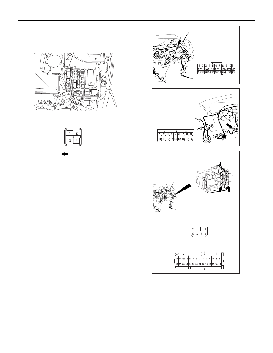
Step 8. Check the wiring harness between B-16X 
A/C compressor relay connector terminal No.3 
and the ignition switch (IG2).

NOTE: 

Prior to the wiring harness inspection, check junction 
block connectors C-202, C-205, joint connector C-01 
and intermediate connector C-17, and repair if 
necessary.

• Check the A/C compressor relay power supply 

line for open circuit.

Q: Is the check result normal?

AC312170

A/C compressor relay

AC

Front of 
vehicle

Connector: B-16X

Relay box side

AC310631AE

Connector: C-01 <RHD>

AC310628AJ

Connector: C-17 <RHD>

AC310619

Connectors: C-202, C-205 <RHD>

AF

Junction block (Front view)

C-205

C-202

C-205

Harness side

C-202

Harness side

TROUBLESHOOTING

HEATER, AIR CONDITIONER AND VENTILATION

55-82

YES : 

The trouble can be an intermittent 

malfunction (Refer to GROUP 00, How to 
Cope with Intermittent Malfunction 

P.00-5

).

NO : 

Repair the wiring harness.

Step 9. Measure the voltage at B-16X A/C 
compressor relay connector.

(1) Remove the relay, and measure at the relay block 

side.

(2) Voltage between terminal 4 and body earth.

OK: System voltage

Q: Is the check result normal?

YES : 

 Go to Step 11.

NO : 

 Go to Step 10.

Step 10. Check the wiring harness between 
B-16X A/C compressor relay connector terminal 
No.4 and the fusible link (26).

NOTE: 

Prior to the wiring harness inspection, check 
intermediate connector A-16, and repair if necessary.

• Check the A/C compressor relay power supply 

line for open circuit.

Q: Is the check result normal?

AC312170

A/C compressor relay

AC

Front of 
vehicle

Connector: B-16X

Relay box side

AC301541HY

Connector B-16X
(Relay box side)

Front of 
vehicle

1

3

2

4

AC312170

A/C compressor relay

AC

Front of 
vehicle

Connector: B-16X

Relay box side

AC310403

AC

Connector: A-16 <LHD>

A-16 (B)

AC310398

AC

Connector: A-16 <RHD>

A-16 (B)

TROUBLESHOOTING

HEATER, AIR CONDITIONER AND VENTILATION

55-83

YES : 

The trouble can be an intermittent 

malfunction (Refer to GROUP 00, How to 
Cope with Intermittent Malfunction 

P.00-5

).

NO : 

Repair the wiring harness.

Step 11. Check the wiring harness between 
B-16X A/C compressor relay connector terminal 
No.2 and C-110 engine-ECU <M/T> or 
engine-A/T-ECU <A/T> connector terminal No.8.

• Check the A/C compressor relay power supply 

line for open circuit.

Q: Is the check result normal?

YES : 

 Go to Step 12.

NO : 

Repair the wiring harness.

Step 12. Check the wiring harness between 
B-16X A/C compressor relay connector terminal 
No.1 and B-120 A/C compressor assembly 
connector terminal No.1.

• Check the A/C compressor power supply line for 

open circuit.

Q: Is the check result normal?

YES : 

The trouble can be an intermittent 

malfunction (Refer to GROUP 00, How to 
Cope with Intermittent Malfunction 

P.00-5

).

NO : 

Repair the wiring harness.

Step 13. Check the magnetic clutch operation.

 Refer to 

P.55-219

.

Q: Can the sound of the magnetic clutch (click) be 

heard?

YES : 

Go to Step 14.

NO : 

Replace the compressor magnet clutch. 

AC312170

A/C compressor relay

AC

Front of 
vehicle

Connector: B-16X

Relay box side

AC310628AH

Harness side

Connector: C-110 <RHD>

C-110 (GR)

AC312170

A/C compressor relay

AC

Front of 
vehicle

Connector: B-16X

Relay box side

AC311221

Connector: B-120 <RHD>

AB

Harness side

B-120 (B)

TROUBLESHOOTING

HEATER, AIR CONDITIONER AND VENTILATION

55-84

Step 14. Check the refrigerant temperature 
switch.

 Refer to 

P.55-221

.

Q: Is the refrigerant temperature switch operating 

properly?

YES : 

Go to Step 15.

NO : 

Replace the refrigerant temperature switch.

Step 15. Check the refrigerant level.

 Refer to 

P.55-193

.

Q: Is the refrigerant level correct?

YES : 

Go to Step 16.

NO : 

Correct the refrigerant level (Refer to 
On-vehicle Service 

P.55-191

). 

Step 16. Replace the A/C-ECU, and then recheck 
the trouble symptom

 Check that the compressor works normally.

Q: Is the check result normal?

YES : 

This diagnosis is complete.

NO : 

Replace the engine-ECU or the 
engine-A/T-ECU.

INSPECTION PROCEDURE 9: The outlet air temperature can not be changed even if the amount of 
solar radiation changes

CIRCUIT OPERATION

When the blower air temperature can not be 
changed even if the amount of solar radiation is 
changed, the photo sensor may be defective. 

POSSIBLE CAUSES

• Malfunction of photo sensor

• Damaged harness wires and connectors

• Malfunction of the A/C-ECU

DIAGNOSIS

Step 1. MUT-III diagnosis code.

Check whether the air conditioner sets a diagnosis 
code or not.

Q: Is the check result normal?

YES : 

Go to Step 2.

NO : 

Refer to diagnosis code chart 

P.55-8

.

Step 2. MUT-III data list.

Check that the following service data display 
contents are normal. (Refer to 

P.55-183

.)

• Item 06: Photo sensor

Q: Is the check result normal?

YES : 

Go to Step 3.

NO : 

Go to Step 4.

STEP 3. Recheck the trouble symptom

Q: Is the check result normal?

Wire colour code
B : Black     LG : Light green     G : Green     L : Blue     W : White     Y : Yellow     SB : Sky blue
BR : Brown     O : Orange     GR : Gray     R : Red     P : Pink     V : Violet

A/C-ECU

PHOTO SENSOR

Photo Sensor Circuit


Content   ..  297  298  299  300   ..