Mitsubishi L200. Manual - part 691


  Index      Mitsubishi     Mitsubishi L200 - service repair manual 2012 year


Search            


Content   ..  689  690  691  692   ..


Mitsubishi L200. Manual - part 691


HEADLAMP

CHASSIS ELECTRICAL

54A-131

DIAGNOSIS PROCEDURE

STEP 1. Connector check: A-58 <headlamp (LO: 
LH)>, A-147 <headlamp (LO: RH)>, A-59 (HI: LH), 
A-146 (HI: RH) headlamp connector

Q: Is the check result normal?

YES : 

Go to Step 2.

NO : 

Repair the defective connector.

STEP 2. Bulb check
Check the bulb(s) of headlamp that does not illumi-
nate.

Q: Is the check result normal?

YES : 

Go to Step 3.

NO : 

Replace the bulb(s) of the lamp that does 
not illuminate.

STEP 3. Resistance measurement at the A-58 
<headlamp (LO: LH)>, A-147 <headlamp (LO: 
RH)>, A-59 (HI: LH),  A-146 (HI: RH) headlamp 
connector

(1) Disconnect the connector, and measure at the 

wiring harness side.

(2) Measure the resistance between the connector of 

lamp which does not illuminate and the body 
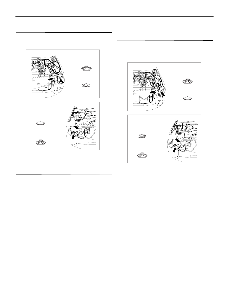
AC903898

AH

Connectors: A-58, A-59

Harness side

A-58

A-59 (B)

Harness side

A-59

A-58 (B)

AC903897

AH

Connectors: A-146, A-147

Harness side

A-146

A-146 (B)

Harness side

A-147

A-147 (B)

AC903898

AH

Connectors: A-58, A-59

Harness side

A-58

A-59 (B)

Harness side

A-59

A-58 (B)

AC903897

AH

Connectors: A-146, A-147

Harness side

A-146

A-146 (B)

Harness side

A-147

A-147 (B)

HEADLAMP

CHASSIS ELECTRICAL

54A-132

earth.

Measure the resistance between the A-58 head-

lamp (LO: LH) connector terminal No. 1 and 
the body earth.

• Measure the resistance between the A-147 

headlamp (LO: RH) connector terminal No. 1 
and the body earth.

Measure the resistance between the A-59 head-

lamp (HI: LH) connector terminal No. 1 and 
the body earth.

• Measure the resistance between the A-146 

headlamp (HI: RH) connector terminal No. 1 
and the body earth.

OK: Continuity exists (2 

 or less)

Q: Is the check result normal?

YES : 

Go to Step 5.

NO : 

Go to Step 4.

STEP 4. Check the wiring harness from A-58 
<headlamp (LO: LH)>, A-147 <headlamp (LO: 
RH)>, A-59 (HI: LH), A-146 (HI: RH) headlamp 
connector (terminal No.1) to body earth

• Check the earth wires for open circuit.

Q: Is the check result normal?

YES : 

The trouble can be an intermittent 

malfunction (Refer to GROUP 00 

− How to 

Use Troubleshooting/inspection Service 
Points 

− How to Cope with Intermittent 

Malfunction ).

NO : 

Repair the wiring harness.

AC310506

Connectors A-58, A-147

(Harness side)

LH

AC310506

Connectors A-59, A-146

(Harness side)

LI

AC903898

AH

Connectors: A-58, A-59

Harness side

A-58

A-59 (B)

Harness side

A-59

A-58 (B)

AC903897

AH

Connectors: A-146, A-147

Harness side

A-146

A-146 (B)

Harness side

A-147

A-147 (B)

HEADLAMP

CHASSIS ELECTRICAL

54A-133

STEP 5. Check the wiring harness from A-58 
<headlamp (LO: LH)>, A-147 <headlamp (LO: 
RH)>, A-59 (HI: LH), A-146 (HI: RH) headlamp 
connector (terminal No.2) to A-22X headlamp 
relay (LO) or A-23X headlamp relay (HI) 
connector (terminal No.3)

• Check the power supply line for open circuit and 

short circuit.

Q: Is the check result normal?

YES : 

Go to Step 6.

NO : 

Repair the wiring harness.

STEP 6. Retest the system
Check that the headlamps illuminate normally.

Q: Is the check result normal?

YES : 

The trouble can be an intermittent 

malfunction (Refer to GROUP 00 

− How to 

Use Troubleshooting/inspection Service 
Points 

− How to Cope with Intermittent 

Malfunction ).

NO : 

Replace the headlamp socket.

AC903878

AG

Connectors: A-22X, A-23X

Relay box side

A-22X, A-23X

A-23X

A-22X

AC903898

AH

Connectors: A-58, A-59

Harness side

A-58

A-59 (B)

Harness side

A-59

A-58 (B)

AC903897

AH

Connectors: A-146, A-147

Harness side

A-146

A-146 (B)

Harness side

A-147

A-147 (B)

HEADLAMP

CHASSIS ELECTRICAL

54A-134

Inspection Procedure 6:  The headlamp automatic-shutdown function does not work normally.

CAUTION

Whenever the ECU is replaced, ensure that the input and output signal circuits are normal.

COMMENTS ON TROUBLE SYMPTOM
The ETACS-ECU operates this function in accord-
ance with the input signals below.

• Ignition switch (IG1)

• Driver's door switch

• Tail lamp switch

• Headlamp switch

If this function does not work normally, these input 
signal circuit(s) or the ETACS-ECU may be defec-
tive.

PROBABLE CAUSES

• Malfunction of the driver's door switch

• Malfunction of the column switch

• Malfunction of the ETACS-ECU

• Damaged harness wires and connectors

DIAGNOSIS PROCEDURE

STEP 1. Check of adjustment details for the 
headlamp automatic-shutdown
Check that the headlamp automatic-shutdown func-
tion is set to "B-spec" using the customise function of 
M.U.T-III.

Q: Is the check result normal?

YES : 

Go to Step 2.

NO : 

Using the customise function of M.U.T-III, 
set the headlamp automatic-shutdown 
function to "B-spec."

STEP 2. M.U.T.-III diagnosis code.
When the ignition switch is turned to the "LOCK" 
(OFF) position, check that the ETACS-ECU does not 
set the diagnosis code.

Q: Is the diagnosis code set?

YES : 

Refer to diagnosis code chart 

P.54A-494

.

NO : 

Go to Step 3.

STEP 3. M.U.T.-III data list
Check the input signals below, which are related to 
the headlamp automatic-shutdown function.

• Turn the ignition switch to the "LOCK" (OFF) 

position.

• Open the drive’s door.

• Turn the headlamp switch to the ON position.

OK: Normal conditions are displayed for all 
the items

Q: Are the check result normal?

AC505478

ETACS-ECU

INPUT SIGNAL

· DRIVER'S DOOR SWITCH

· TAIL LAMP SWITCH (COLUMN-ECU)

· IGNITION SWITCH (IG1)

· HEADLAMP SWITCH (COLUMN-ECU)

Headlamp Automatic Shutdown Function

AB

Item 
No.

Item name

Normal condition

19

Drive’s door switch

ON

30

Ignition switch(IG1)

OFF

60

Headlamp output

ON


Content   ..  689  690  691  692   ..