Mitsubishi L200. Manual - part 652


  Index      Mitsubishi     Mitsubishi L200 - service repair manual 2012 year


Search            


Content   ..  650  651  652  653   ..


Mitsubishi L200. Manual - part 652


CURTAIN AIR BAG MODULE(S) <VEHICLES WITH SIDE-AIRBAG AND CURTAIN AIR BAG>

SUPPLEMENTAL RESTRAINT SYSTEM (SRS)

52B-279

CURTAIN AIR BAG MODULE(S) <VEHICLES WITH SIDE-

AIRBAG AND CURTAIN AIR BAG>

 REMOVAL AND INSTALLATION 

M1524013500523

WARNING

Disconnect the negative battery terminal and wait for 60 seconds or more before starting 
work. Furthermore, the disconnected battery terminal should be covered with tape to 
insulate it.

Never attempt to disassemble or repair the air bag modules. If faulty, replace it.

Do not drop the air bag modules or allow contact with water, grease or oil. Replace it if a 
dent, crack, deformation or rust is detected.

The removed air bag module should be stored in a clean, dry place with the deployment 
surface facing up. Do not place anything on top of it.

Do not expose the air bag modules to temperatures over 93

°

C.

After deployment of an air bag, the air bag module has been replaced with a new one.

Wear gloves and safety glasses when handling air bags that have already deployed.

An undeployed air bag module should only be disposed of in accordance with the proce-
dures (Refer to 

P.52B-289

).

Pre-removal Operation
• Turn the ignition switch to the LOCK (OFF) position.

• Disconnect the negative (−) battery terminal.
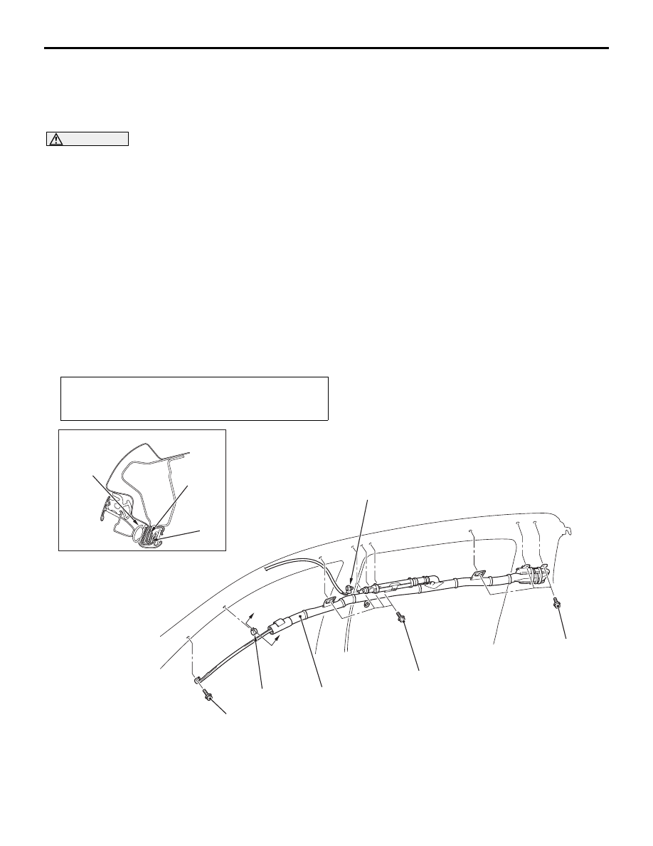
AC800575

1

2

AB

10 ± 4 N·m

10 ± 4 N·m

3

10 ± 4 N·m

A

A

Section A - A

Door opening 
weatherstrip 
inner

2

3

Removal steps 

Headlining (Refer to GROUP 52A, 
Headlining ).

<<

A

>>

1.

Curtain air bag module harness 
side connector

<<

B

>>

2.

Curtain air bag module

3.

Headlining bracket
Installation steps 

>>

A

<<

Pre-installation inspection

3.

Headlining bracket

Removal steps (Continued)

CURTAIN AIR BAG MODULE(S) <VEHICLES WITH SIDE-AIRBAG AND CURTAIN AIR BAG>

SUPPLEMENTAL RESTRAINT SYSTEM (SRS)

52B-280

REMOVAL SERVICE POINTS

<<A>> CURTAIN AIR BAG MODULE HARNESS 
SIDE CONNECTOR REMOVAL

AC611205AC

Inflator

Curtain air bag 
module harness 
side connector

Locking button

Flat-tipped 
screwdriver

Use the flat-tipped screwdriver to pull out the locking 
button of curtain air bag harness side connector, and 
release the lock.

<<B>> CURTAIN AIR BAG MODULE REMOVAL

CAUTION

• Never use an electric tester to diagnose the 

air bag module circuit. Never attempt to dis-
assemble the air bag module.

• The removed air bag module should be stored 

in a clean, dry place.

• When discarding the air bag module, discard 

after deploying the air bag as specified in the 
service procedure (Refer to 

P.52B-289

).

INSTALLATION SERVICE POINTS

>>A<< PRE-INSTALLATION INSPECTION
1. Before the installation, check the air bag module 

(Refer to 

P.52B-281

).

NOTE: Even when installing a new air bag mod-
ule, perform an inspection before the installation.

2. Connect the negative (

−) battery terminal.

AC509179

AB

Diagnosis

connector

MB991827

MB991824 

MB991910

<LH drive vehicles>

CAUTION

Be sure to turn the ignition key to the LOCK 
(OFF) position when connecting or disconnect-
ing M.U.T.-III.
3. Connect M.U.T.-III to the diagnosis connector (16 

pin).

4. Turn the ignition switch to the ON position.
5. Read the diagnosis code, and check that 

everything is normal except the air bag module 
open circuit.

6. Turn the ignition switch to the LOCK (OFF) 

position.

>>B<< CURTAIN AIR BAG MODULE 
INSTALLATION

CAUTION

• Take care not to contort the curtain air bag 

when installing it.

• Do not trap the air bag with the peripheral 

parts.

• Do not trap the strap with the front pillar trim 

clip or others.

>>C<< CURTAIN AIR BAG MODULE HARNESS 
SIDE CONNECTOR INSTALLATION

CAUTION

Connect the connector to the inflator thoroughly.

>>D<< POST-INSTALLATION INSPECTION
1. Connect the negative battery cable.
2. Turn the ignition switch to “ON” position.

>>

B

<<

2.

Curtain air bag module

>>

C

<<

1.

Curtain air bag module harness 
side connector

Headlining (Refer to GROUP 52A, 
Headlining ).

>>

D

<<

Post-installation inspection

Installation steps (Continued)

AC900540 AB

SRS warning lamp

CURTAIN AIR BAG MODULE(S) <VEHICLES WITH SIDE-AIRBAG AND CURTAIN AIR BAG>

SUPPLEMENTAL RESTRAINT SYSTEM (SRS)

52B-281

3. Does the "SRS" warning lamp illuminate for 

approximately seven seconds, and go out?

4. If no, refer to troubleshooting (Refer to 

P.52B-12

).

INSPECTION

M1524013600241

AC800743

Curtain air bag module 
deployment section

AB

CAUTION

• Never measure the curtain air bag module cir-

cuit resistance even with the specified tester. 
Measuring the circuit resistance with a tester 
causes accidental air bag deployment due to 
current that flows or static, resulting in seri-
ous personal injury.

• When replacing the parts, discard the old 

parts after deploying the air bag according to 
the specified procedure (Refer to 

P.52B-289

).

• There must be no abnormality to the curtain 

air bag deployment section of headlining.

1. Crack, dent or deformation to inflator surface
2. Torn air bag
3. Damaged connector, deformation of terminal, 

and harness binding

SIDE IMPACT SENSOR <VEHICLES WITH SIDE-AIRBAG AND CURTAIN AIR BAG>

SUPPLEMENTAL RESTRAINT SYSTEM (SRS)

52B-282

SIDE IMPACT SENSOR <VEHICLES WITH SIDE-AIRBAG 

AND CURTAIN AIR BAG>

REMOVAL AND INSTALLATION 

M1524004601213

WARNING

Disconnect the negative battery terminal and wait for 60 seconds or more before starting 
work. Furthermore, the disconnected battery terminal should be covered with tape to 
insulate it.

Never attempt to disassemble or repair the side impact sensor. If faulty, replace it.

Do not drop or subject the side impact sensor to impact or vibration. If denting, cracking, 
deformation, or rust are discovered in the side impact sensor, replace it with a new side 
impact sensor. Discard the old one.

After deployment of an air bag, replace the side impact sensor with a new one.

Never use an ohmmeter on or near the side impact sensor, and use only the special test 
equipment described on 

P.52B-11

.

Pre-removal Operation
• Turn the ignition switch to the "LOCK" (OFF) position.
• Disconnect the Negative (−) Battery Terminal.

AC801140

2

AB

1

11 ± 2 N·m 

Removal steps 

Centre pillar lower trim <Double 
cab> (Refer to GROUP 52A, Trims 
).

Quarter lower trim <Club cab> 
(Refer to GROUP 52A, Trims ).

Seat belt retractor (Refer to 

P.52B-

284

).

1.

Side impact sensor

<<

A

>>

2.

Side impact sensor harness side 
connector
Installation steps 

>>

A

<<

Pre-installation inspection

2.

Side impact sensor harness side 
connector

>>

B

<<

1.

Side impact sensor

Seat belt retractor (Refer to 

P.52B-

284

).

Quarter lower trim <Club cab> 
(Refer to GROUP 52A, Trims ).

Centre pillar lower trim <Double 
cab> (Refer to GROUP 52A, Trims 
).

>>

C

<<

Post-installation inspection

NOTE: The figure shows the right side impact sen-
sor.

Installation steps (Continued)


Content   ..  650  651  652  653   ..