Mitsubishi L200. Manual - part 407
STRUT BAR <2WD (except High rider)>
FRONT SUSPENSION
33-24
STRUT BAR <2WD (except High rider)>
REMOVAL AND INSTALLATION
M1332011900043
CAUTION
*: Indicates parts which should be temporarily tightened, and then fully tightened with the vehicle on
the earth in an unladen condition.
Post-installation Operation
• Front Wheel Alignment Check and Adjustment (Refer to
).
AC501901AB
162 ± 24 N·m
1
2
2
3
4
6
5
162 ± 24 N·m
98 ± 12 N·m*
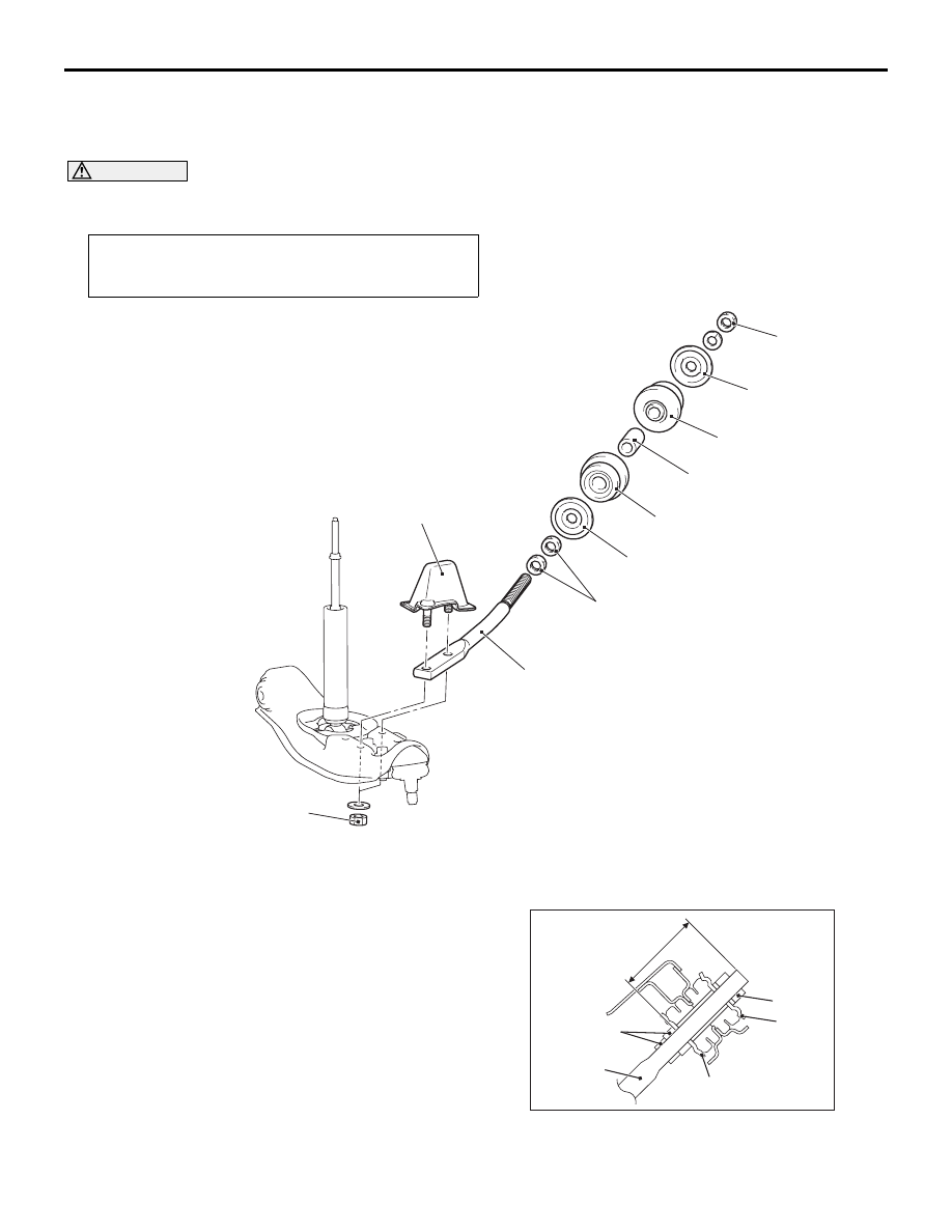
Removal steps
>>
A
<< 1.
Washer
>>
A
<< 2.
Strut bar bushing
3.
Collar
>>
A
<< 4.
Washer
5.
Bump stopper
6.
Strut bar
INSTALLATION SERVICE POINT
>>A<< WASHER/STRUT BAR BUSHING INSTAL-
LATION
AC502815
Strut bar
AB
Nut
Washer
Nuts
Washer
A
1. Install the washer and strut bar bushing to the
direction as shown in the figure.