Mitsubishi L200. Manual - part 396


  Index      Mitsubishi     Mitsubishi L200 - service repair manual 2012 year


Search            


Content   ..  394  395  396  397   ..


Mitsubishi L200. Manual - part 396


Bearing type

Bearing 
lubrication

Turning torque

New

None (with anti-
rust agent)

0.59 

− 0.88 N⋅m

New or reuse

Gear oil applied 0.39 

− 0.49 N⋅m

DIFFERENTIAL CARRIER ASSEMBLY

REAR AXLE

27-35

NOTE: Because special tool preload socket 
(MB990326) cannot be turned one turn, turn it 
several times within the range that it can be 
turned; then, after fitting to the bearing, measure 
the turning torque.

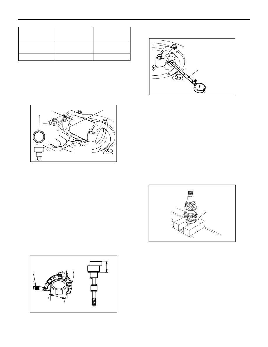
4. Clean the side bearing hub.

ACX01109 AL

Notch

A

Thickness
gauge

MB990820
(MB990819) or MB991169

MB991170,
MB991534

5. Place the following special tools between the side 

bearing hub of the gear carrier, and position the 
notch as shown in the illustration. Then tighten 
side bearing mounting bolt.

• Cylinder gauge (MB991170) <5A/T or except 

vehicles with High power engine>

• Cylinder gauge (MB991534) <Vehicles with High 

power engine except 5A/T>

• Pinion [MB990820 (MB990819)] <2WD (except 

High rider)>

• Drive pinion gauge attachment (MB991169) 

<2WD High rider, 4WD>

6. Use a thickness gauge to measure the clearance 

(A) between the special tools.

7. Remove the special tools.

AC102913

C

B

AC

8. Use a micrometer to measure the shown 

dimensions (B, C) of special tools.

AC102914

Cylinder gauge

AC

D

9. Install the bearing cap, and then use a cylinder 

gauge to measure the inside diameter (D) of the 
bearing cap.

10.Calculate thickness (F) of the required drive 

pinion rear shim twice by the following formula. 
Select a shim which most closely matches this 
thickness.
F = A + B + C 

 1/2D  100.00 mm <2WD 

(except High rider)>

F = A + B + C 

 1/2D  115.00 mm <2WD High 

rider, 5A/T or except vehicles with High 
power engine>

F = A + B + C 

 1/2D  120.00 mm <Vehicles 

with High power engine except 5A/T>

ACX02428 AE

Drive pinion
rear shim

MB990802

11.Fit the selected drive pinion rear shim(s) to the 

drive pinion, and press-fit the drive pinion rear 
bearing inner race by using special tool bearing 
installer (MB990802).

>>D<< DRIVE PINION PRELOAD ADJUSTMENT
1. Insert the drive pinion into the gear carrier, and 

then install the following parts in sequence from 
the carrier rear side. Drive pinion spacer, drive 
pinion front shim and drive pinion front bearing 
inner race, companion flange.
NOTE: Do not install the oil seal.

AC201179 AB

MB990850

DIFFERENTIAL CARRIER ASSEMBLY

REAR AXLE

27-36

2. Tighten the companion flange to the specified 

torque by using special tool end yoke holder 
(MB990850).

Tightening torque: 216 

± 29 Nm

ACX01062AB

MB990326

MB990685

3. Use the following special tools to measure the 

drive pinion turning torque (without oil seal).

• Preload socket (MB990326)

• Torque wrench (MB990685)

Standard value:

Bearing type

Bearing 
lubrication

Turning torque

New

None (with anti-
rust agent)

0.59 

− 0.88 N⋅m

New or reuse

Gear oil applied 0.39 

− 0.49 N⋅m

ACX01063

Identifi-
cation
colour

A

AE

4. If the drive pinion turning torque is not within the 

standard value, adjust the turning torque by 
replacing the drive pinion front shim(s) or the drive 
pinion spacer.

NOTE: When selecting the drive pinion front 
shims, if the number of shims is large, reduce the 
number of shims to a minimum by selecting the 
drive pinion spacers.
Also, select the drive pinion spacer from the fol-
lowing two types.

Height of drive 
pinion spacer 
(A) mm

Identification 
colour

Applicable 
model

56.67

5A/T or except 
vehicles with 
High power 
engine

57.01

White

52.50

Yellow

Vehicles with 
High power 
engine except 
5A/T

52.84

Red

ACX01064 AD

MB991168

5. Remove the companion flange and drive pinion 

again. Then insert the drive pinion front bearing 
inner race into the gear carrier. Use special tool 
differential oil seal installer (MB991168) to press-
fit the oil seal.

AC201179 AB

MB990850

6. Install the drive pinion assembly and companion 

flange with mating marks properly aligned. 
Tighten the companion flange self-locking nut to 
the specified torque using special tool end yoke 
holder (MB990850).

Tightening torque: 216 

± 29 Nm

ACX01062AB

MB990326

MB990685

DIFFERENTIAL CARRIER ASSEMBLY

REAR AXLE

27-37

7. Use special tools to measure the drive pinion 

turning torque (with oil seal) to verify that the drive 
pinion turning torque complies with the standard 
value.

Standard value:

Bearing 
division

Companion 
flange 
lubrication

Turning torque

New

None (with anti-
rust agent)

0.84 

− 1.12 N⋅m

Gear oil applied 0.64 

− 0.73 N⋅m

8. If the turning torque is not within the standard 

value, check the tightening torque of the 
companion flange self-locking nut, and the 
installation of the oil seal.

>>E<< DIFFERENTIAL GEAR BACKLASH 
ADJUSTMENT
Adjust the differential gear backlash by the following 
procedure:

ACX01066

1. Assemble the side gears, side gear thrust 

spacers, pinion gears, and pinion washers into the 
differential case.

2. Temporarily install the pinion shaft.

NOTE: Do not assemble the thrust block and lock 
pin yet.

ACX01035 AB

Wedge

Side gear
thrust spacer

Side gear
thrust 
spacer

3. Insert a wedge between the side gear and the 

pinion shaft to lock the side gear.

4. While locking the side gear with the wedge, 

measure the differential gear backlash with a dial 
indicator on the pinion gear.

Standard value: 0.01 

 0.25 mm

5. Measure by the same procedure for the other 

pinion gear.

6. If the backlash exceeds the limit value, replace 

side bearing adjustment spacers.

7. If adjustment is not possible, replace the side 

gears and pinion gears as a set.

8. Check that the backlash is within the limit value 

and that the differential gear turns smoothly.

>>F<< LOCK PIN INSTALLATION
1. Align the pinion shaft lock pin hole with the 

differential case lock pin hole, and drive in the lock 
pin.

ACX02429

2. Stake the lock pin with a punch on both sides.

>>G<< DRIVE GEAR INSTALLATION
1. Clean the drive gear attaching bolts.

ACX01068AB

Tap

DIFFERENTIAL CARRIER ASSEMBLY

REAR AXLE

27-38

2. Remove the adhesive adhered to the threaded 

holes of the drive gear by turning the tap (M10 x 
1.25). Clean the threaded holes by applying 
compressed air.

ACX02430

3. Apply specified adhesive to the threaded holes of 

the drive gear.

Specified adhesive: LOCTITE No.271 or 
No.270 or equivalent

4. Install the drive gear onto the differential case with 

the mating marks properly aligned. Tighten the 
bolts to the specified torque in a diagonal 
sequence.

Tightening torque:

84 

± 5 Nm <5A/T or except vehicles with High 

power engine>

152 

± 15 Nm <Vehicles with High power 

engine except 5A/T>

>>H<< SIDE BEARING INNER RACE 
INSTALLATION

AC102942

AC

MB990728

Piece of
metal

Piece of 
metal

Use special tool side and rear bearing inner race 
installer (MB990728) to press-fit the side bearing 
inner races into the differential case.

>>I<< BEARING CAP INSTALLATION

AC004945 AB

74 ± 4 N·m

Align the mating marks on the gear carrier and the 
bearing cap, and then tighten the bearing cap.

>>J<< DRIVE GEAR BACKLASH ADJUSTMENT
Adjust drive gear backlash as follows:

AC004921AB

MB991385

MB991367

1. Using the following special tools, temporarily 

tighten the side bearing nut to just before 
preloading of the side bearing.

• Special spanner (MB991367)

AC004946 AB

Pin (MB991385)

2. Measure the drive gear backlash.

Standard value:

0.07 

 0.13 mm <2WD (except High rider)>

0.08 

 0.18 mm <2WD High rider, 4WD>


Content   ..  394  395  396  397   ..