Mitsubishi L200. Manual - part 53
GENERAL INFORMATION
DIESEL FUEL
13A-8
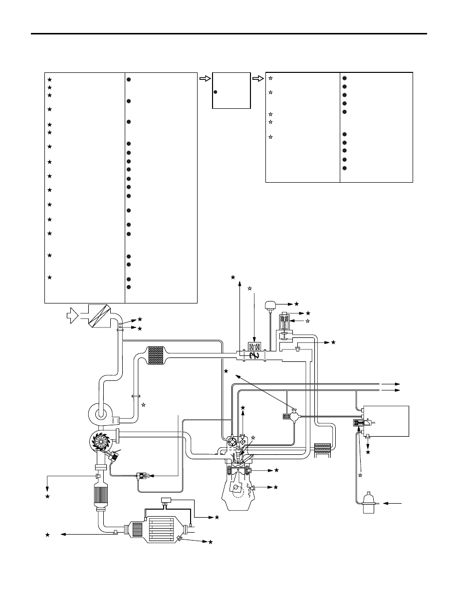
FUEL INJECTION SYSTEM DIAGRAM
<Euro5>
AKB00240
Variable geometry
actuator
2 Crank angle sensor
4 Engine coolant
temperature sensor
3 Camshaft
position
sensor
6 Intake air temperature
sensor No. 1
Air
1 Air flow sensor
3 Injector
5 Rail pressure sensor
1 Suction control
valve
9 Fuel
temperature
sensor
From fuel
tank
To fuel tank
Supply
pump
To brake system
Fuel filter
AB
12
13
5 Variable geometry
control solenoid valve
1 Air flow sensor
2 Crank angle sensor
3 Camshaft position
sensor
4 Engine coolant
temperature sensor
5 Rail pressure sensor
6 Intake air temperature
sensor No. 1
7 EGR gas temperature
sensor
8 Manifold absolute
pressure sensor
9 Fuel temperature
sensor
10 Throttle position
sensor
11 EGR valve
position sensor
12 No. 1 exhaust gas
temperature sensor
13 No. 2 exhaust gas
temperature sensor
(catalyst temperature)
14 No. 3 exhaust gas
temperature sensor
(DPF temperature)
15 Exhaust differential
pressure sensor
Accelerator pedal
position sensor
(main)
Accelerator pedal
position sensor
(sub)
Power steering
fluid pressure
switch
Power supply
Vehicle speed sensor
Ignition switch-IG
Ignition switch-ST
A/C switch
A/C load signal
PTC heater control
signal <Vehicles
with PTC heater>
Back-up lamp
switch <M/T>
4LLC switch <M/T>
Battery current sensor
Battery temperature
sensor
Glow diagnosis signal
CAN communication
(input signal)
CAN communication
(output signal)
1st and 2nd rail switch
<M/T>
Engine-
ECU
Barometric
pressure
sensor
Engine control relay
A/C relay
Condenser fan relay
Glow control unit
PTC heater relay
<Vehicles with
PTC heater>
1 Suction control
valve
2 Throttle valve
control servo
(DC motor)
3 Injector
4 EGR valve
(DC motor)
5 Variable geometry
control solenoid
valve
Alternator G terminal
Glow indicator lamp
Engine warning lamp
Tachometer
4 EGR valve (DC motor)
8 Manifold absolute pressure sensor
2 Throttle valve control servo (DC motor)
10 Throttle position sensor
7 EGR gas temperature
sensor
11 EGR valve position sensor
No. 1 exhaust
gas temperature
sensor
No. 2 exhaust gas
temperature sensor
14 No. 3 exhaust gas temperature sensor
(catalyst temperature)
(DPF temperature)
15 Exhaust differential pressure sensor
Catalytic
converter
Catalytic
converter
DPF