Mazda Training manual - part 6


  Index      Mazda     Mazda Training Manual


Search            


Content   ..  4  5  6  7   ..


Mazda Training manual - part 6


Powertrain Engines 

Balancer Shaft Unit 

• 

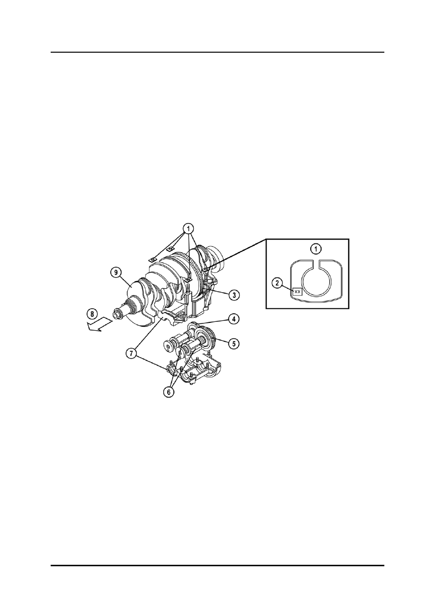
The balancer shafts minimize the engine vibrations by rotating at twice the speed of the 
crankshaft. 

• 

The balancer shaft unit features a two-piece housing, which is fixed to the cylinder block 
by four bolts. 


NOTE:  The balancer shaft unit cannot be repaired due to its precise interior construction, i.e. 

it must be replaced as a complete unit. 

 
• 

If the cylinder block, crankshaft, crankshaft main bearing, or balancer shaft unit have 
been replaced, the backlash between the drive gear of the crankshaft and the driven 
gear of the balancer shaft unit must be adjusted using shims (refer to the workshop 
manual for details). 


L1001.4_01006 


Adjustment shim 

Counter weights 

Engraved identification mark 

Balancer shaft unit housing 

Drive gear 

Engine front side 

4 Balancer 

shaft 

no.2 

9 Crankshaft 

Balancer shaft no.1 with driven gear 


Curriculum Training 

01-11 

Engines Powertrain 

Cylinder Head 

• 

The cylinder head is a conventional construction with separate camshaft bearing caps. 

• 

The cylinder head bolts are torque-to-yield bolts, which must be tightened in several 
stages (refer to the workshop manual for details). 


NOTE:  The cylinder head bolts must not be re-used if their length exceeds the specification 

(refer to the workshop manual for details). 


L1001.4_01007 


Exhaust side 

Exhaust port 

Cylinder head bolt 

Intake side 

Intake port 

Engine front side 


01-12 Curriculum 

Training 

Powertrain Engines 

Camshafts 

• 

The camshafts feature no key for the installation of the camshaft sprockets, i.e. solely 
the clamping force of the lock bolt secures the sprocket on the camshaft. 

• 

The intake camshaft of the LF and L3 engine is equipped with an oil line supplying oil to 
the camshaft actuator of the variable valve timing system. 

• 

The intake camshaft has a pulse wheel for the CMP (Camshaft Position) sensor signals. 


L1001.4_01008 


Exhaust camshaft 

Cam nose 

Thrust collar 

Pulse wheel for CMP sensor 

Cam heel 

Intake camshaft  
(with variable valve timing system) 

Cam journal 

Intake camshaft front end (without 
variable valve timing system) 


Curriculum Training 

01-13 

Engines Powertrain 

Valve Actuation 

• 

The camshafts actuate the valves via mechanical bucket tappets without adjustment 
shims. 

• 

The valve clearance is adjusted by the different thickness of the bucket tappets. The 
tappet thickness can be determined by the engraved number (e.g. number “402” means 
a thickness of 3.402 mm). In order to replace the tappets the camshafts have to be 
removed (refer to the workshop manual for details). 

• 

The valve clearance has to be audibly inspected (and if noisy adjusted) every 120,000 
km.


L1001.4_01009 


1 Camshaft 

4 Tappet 

thickness 

2 Tappet 

cross-sectional 

view 

Valve stem contact surface 

Cam lobe contact surface 

Bucket tappet 


01-14 Curriculum 

Training 


Content   ..  4  5  6  7   ..