Mazda engine MZR–CD. Manual - part 12


  Index      Mazda     Mazda engine MZR–CD - service manual 2002 year


Search            


Content   ..  10  11  12  13   ..


Mazda engine MZR–CD. Manual - part 12


B–28

ENGINE 

VALVE CLEARANCE INSPECTION

AME222412111105

1. Remove the cylinder head cover.
2. Turn the crankshaft and align the timing marks so that the piston of the No.1 or No.4 cylinder is at TDC of 

compression.

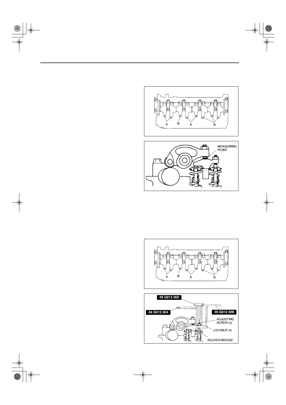
3. Measure the valve clearances A with the No.1 

cylinder at TDC of compression, and those of B 
with the No.4 cylinder at TDC of compression.

Standard valve clearance [Engine cold]

IN: 0.12—0.18 mm {0.0048—0.0070 in} 

(0.15

±±±±

0.03 mm {0.0059

±±±±

0.0012 in})

EX: 0.32—0.38 mm {0.0126—0.0149 in} 

(0.35

±±±±

0.03 mm {0.0138

±±±±

0.0012 in})

4.  If the valve clearance is not within the 

specification, adjust the valve clearance. (See 

B–

28 VALVE CLEARANCE ADJUSTMENT

)

5. Turn the crankshaft one full turn and measure the 

remaining valve clearances. Adjust the valve 
clearance if necessary.

End Of Sie

VALVE CLEARANCE ADJUSTMENT

AME222412111106

1. Remove the injection nozzle bracket.
2. Remove the injection nozzle.

Caution

••••

When removing the injection nozzle bracket, always replace the injection nozzle washer. When 
replacing the injection nozzle washer, wipe off any carbon adhering to the nozzle installation 
surface of the cylinder head with a clean cloth before installing.

3. Turn the crankshaft clockwise and set the No.1 

cylinder to compression TDC.

4. Adjust the valve clearance A with the No.1 

cylinder at TDC of compression, and those of B 
with the No.4 cylinder at TDC compression.
(1) Hold the rocker bridge using the SST (49 

G012 006).

(2) Loosen the locknut (d) using the SST (49 

G012 004), and then turn the adjusting screw 
(c) using the SST (49 G012 005) until it is 
separated from the valve stem completely.

AME2512E001

AME2512E002

AME2512E001

AME2512E003

ENGINE 

B–29

B

(3) Loosen the rocker arm locknut (b) using the 

SST (49 G012 004), and then turn the 
adjusting screw (a) using the SST (49 G012 
005) until it is separated from the rocker 
bridge completely.

(4) Insert a feeler gauge between the rocker arm 

and rocker bridge (e).

Standard valve clearance [Engine cold]

IN: 0.12—0.18 mm {0.0048—0.0070 in} 

(0.15

±±±±

0.03 mm {0.0059

±±±±

0.0012 in})

EX: 0.32—0.38 mm {0.0126—0.0149 in} 

(0.35

±±±±

0.03 mm {0.0138

±±±±

0.0012 in})

(5) Adjust the valve clearance by turning the 

adjuster (a) using the  SST (49 G012 005).
Then temporarily tighten locknut (b) using the  
SST
 (49 G012 004).

(6) With the feeler gauge inserted between the 

rocker arm end rocker bridge, verify that the 
feeler gauge remains firmly in place even 
when the adjusting screw (c) is loosened. If 
the feeler gauge does not remain firmly in 
place, repeat procedures from Step 1.

(7) Turn the adjusting screw (c) using the SST 

(49 G012 005) until it reaches the valve stem 
and the feeler gauge fits more firmly.
Then tighten the locknut (d) using the SST (49 
G012 004) to specified torque.

Tightening torque

16—20 N·m {1.6—2.1 kgf·cm, 12—15 in·lbf}

(8) Loosen the locknut (b) using the SST (49 G012 004) and readjust the valve clearance (e).

Standard valve clearance [Engine cold]

IN: 0.12—0.18 mm {0.0048—0.0070 in} (0.15

±±±±

0.03 mm {0.0059

±±±±

0.0012 in})

EX: 0.32—0.38 mm {0.0126—0.0149 in} (0.35

±±±±

0.03 mm {0.0138

±±±±

0.0012 in})

(9) Tighten the locknut (b) using the SST (49 G012 004) to specified torque.

Tightening torque

16—20 N·m {1.6—2.1 kgf·cm, 12—15 in·lbf}

(10)Verify the valve clearance at (e).

Standard valve clearance [Engine cold]

IN: 0.12—0.18 mm {0.0048—0.0070 in} (0.15

±±±±

0.03 mm {0.0059

±±±±

0.0012 in})

EX: 0.32—0.38 mm {0.0126—0.0149 in} (0.35

±±±±

0.03 mm {0.0138

±±±±

0.0012 in})

5. Turn the crankshaft one full turn and adjust the remaining valve clearances.
6. Install the injection nozzle.
7. Install the injection nozzle bracket.

(See 

B–41 Injection Nozzle Assembly Note

)

End Of Sie

AME2512E004

AME2512E005

B–30

ENGINE 

CYLINDER BLOCK (I) ASSEMBLY

1. Assemble in the order indicated in the table.

.

AME2524E075

1

Cylinder block

2

Oil  jet

3

Upper main bearing, thrust bearing

4

Crankshaft

5

Lower main bearing, thrust bearing

6

Main bearing cap
(See 

B–31 Main Bearing Cap Assembly Note

)

7

Piston
(See 

B–31 Piston Assembly Note

)

8

Connecting rod

9

Piston  Pin

10

Snap ring

11

Piston ring
(See 

B–31 Piston Ring Assembly Note

)

12

Connecting rod, piston
(See 

B–31 Piston Ring Assembly Note

)

13

Connecting rod bearing

14

Connecting rod cap 
(See 

B–32 Connecting Rod Cap Assembly Note

)

15

Cover

ENGINE 

B–31

B

Main Bearing Cap Assembly Note

1. Tighten the bolts in the order shown.

2.

Piston Assembly Note

1. Assemble the piston and the connecting rod in 

the direction from which they were disassembled.

2. Apply clean engine oil to the piston pin.
3. Install the piston pin until the pin contacts the clip. 

If the pin cannot be installed easily, heat the 
piston.

Piston Ring Assembly Note

1. Install the first and second rings as shown.

Connecting Rod, Piston Assembly Note

1. Insert the piston and connecting rod into the 

cylinder with the F mark facing the front of the 
engine.

AME2524E067

AME2524E036

AME2524E037

AME2524E062


Content   ..  10  11  12  13   ..