Mazda Transaxle G35M–R. Manual - part 9


  Index      Mazda     Mazda Transaxle G35M–R - service manual 2002 year


Search            


Content   ..  7  8  9  10   ..


Mazda Transaxle G35M–R. Manual - part 9


MANUAL TRANSAXLE 

J–17

J

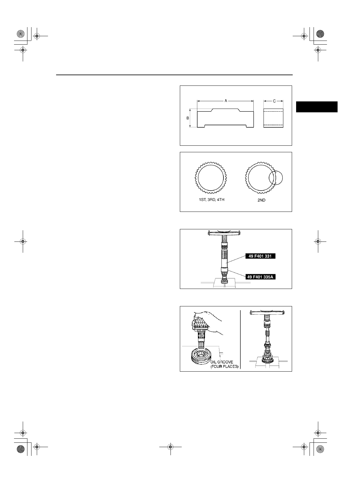
3rd/4th Clutch Hub Assembly Note

1. Install the synchronizer key springs in the clutch 

hub with the hooks in the grooves to hold the 
three synchronizer key in place.

Synchronizer key size

A: 17.0 mm {0.669 in}
B: 4.3 mm {0.17 in}
C: 5.0 mm {0.20 in}

2. Align the synchronizer ring grooves with the 

synchronizer key during assembly.

Bearing (Primary Shaft End) Assembly Note

1. Install the new bearing using the SST.

3rd Gear, 3rd Synchronizer Ring, and 3rd/4th Clutch Hub Component Assembly Note

1. Install the 3rd gear, 3rd synchronizer ring, and 

3rd/4th clutch hub component using a press.

A6E5110M131

Z4F5112M032

Z4F5112M033

Z4F5112M034

J–18

MANUAL TRANSAXLE 

4th Synchronizer Ring, 4th Gear, and Bearing (4th Gear End) Assembly Note

1. Install the 4th synchronizer ring, 4th gear, and a 

new bearing using the SST.

2. Measure the clearance between the 3rd gear and 

2nd gear.

If not as specified, reassemble the primary 
shaft component.

Clearance

0.05—0.20 mm {0.002—0.007 in}

Maximum

0.25 mm {0.010 in}

3. Measure the clearance between the 4th gear and 

bearing.

If not as specified, reassemble the primary 
shaft component.

Clearance

0.17—0.37 mm {0.007—0.014 in}

Maximum

0.42 mm {0.017 in}

End Of Sie

SECONDARY SHAFT COMPONENTS PREINSPECTION

A6E511217301M01

1st Gear Thrust Clearance Inspection

1. Measure the clearance between 1st gear and the 

differential drive gear.

If the clearance exceeds the maximum, check 
the contact surfaces of the 1st gear, 
differential drive gear of the secondary shaft 
gear, and 1st/2nd clutch hub component. 
Replace worn and damaged parts.

Clearance

0.05—0.28 mm {0.002—0.011 in}

Maximum

0.33 mm {0.013 in}

Z4F5112M035

A6E5112M036

A6E5112M037

A6E5112M038

MANUAL TRANSAXLE 

J–19

J

2nd Gear Thrust Clearance Inspection

1. Measure the clearance between 2nd gear and 

secondary 3rd gear.

If the clearance exceeds the maximum, check 
the contact surfaces of the 2nd gear, 
secondary 3rd gear, and 1st/2nd clutch hub 
component. Replace worn and damaged 
parts.

Clearance

0.18—0.46 mm {0.007—0.018 in}

Maximum

0.51 mm {0.020 in}

End Of Sie

A6E5112M039

J–20

MANUAL TRANSAXLE 

SECONDARY SHAFT COMPONENTS DISASSEMBLY

A6E511217301M02

1. Disassemble in the order shown in the figure.

.

A6E5112M111

1

Bearing
(See 

J–21 Bearing and Secondary 4th Gear 

Disassembly Note

)

2

Secondary 4th gear

3

Retaining ring

4

Secondary 3rd gear
(See 

J–21 Secondary 3rd Gear and 2nd Gear 

Disassembly Note

)

5

Friction damper

6

Inner cone

7

Double cone

8

2nd gear

9

Synchronizer ring

10

Retaining ring

11

1st/2nd clutch hub component
(See 

J–21 1st/2nd Clutch Hub Component, 1st 

Synchronizer Ring, and 1st Gear Disassembly Note

)

12

1st gear

13

Synchronizer ring

14

Inner cone

15

Double cone

16

Bearing
(See 

J–21 Bearing (Secondary Shaft End) 

Disassembly Note

)

17

Secondary shaft gear

18

Synchronizer key springs

19

Clutch hub sleeve (reverse gear)

20

Synchronizer keys

21

1st/2nd clutch hub


Content   ..  7  8  9  10   ..