Mazda CX-9 Grand Touring. Manual - part 265
DTC P0351, 0352, 0353, 0354, 0355, 0356 [MZI-3.7]
DTC P0351, 0352, 0353, 0354, 0355, 0356 (MZI-3.7) DETECTION CONDITIONS AND POSSIBLE
CAUSES
9
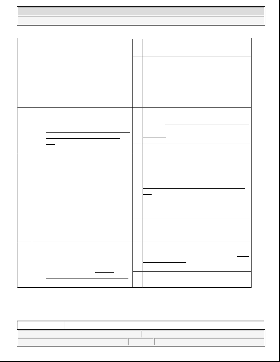
FOR OPEN CIRCUIT
Turn the ignition switch off.
Check continuity between the
following circuits:
CMP sensor (LH) terminal A
and PCM terminal 2AB
CMP sensor (LH) terminal B
and PCM terminal 2C
Is there continuity?
Yes Go to the next step.
No
Repair or replace suspected part, then go to Step
11.
10
INSPECT CMP SENSOR (LH)
Inspect CMP sensor (LH). (See
CRANKSHAFT POSITION (CKP)
SENSOR INSPECTION [MZI-
3.7] .)
Is there any malfunction?
Yes
Replace CMP sensor (LH), then go to the next
step. (See CRANKSHAFT POSITION (CKP)
SENSOR REMOVAL/INSTALLATION
[MZI-3.7] .)
No
Go to the next step.
11
VERIFY TROUBLESHOOTING OF
DTC P0349 COMPLETED
Verify that all disconnected
connectors reconnected.
Turn ignition switch to the ON
position (Engine off).
Clear the DTC from the PCM memory
using the M-MDS.
Start the engine.
Access the MAF PID using the M-
MDS.
Is same DTC present?
Yes
Replace the PCM, then go to the next step. (See
PCM REMOVAL/INSTALLATION [MZI-
3.7] .)
No
Go to the next step.
12
VERIFY AFTER REPAIR
PROCEDURE
Perform the "AFTER REPAIR
PROCEDURE". (See AFTER
REPAIR PROCEDURE [MZI-3.7].)
Are any DTC present?
Yes
Go to the applicable DTC inspection. (See DTC
TABLE [MZI-3.7].)
No
Troubleshooting completed.
DTC P0351
P0351: Ignition coil No.1 primary/secondary circuit
2008 Mazda CX-9 Grand Touring
2008 ENGINE PERFORMANCE On-Board Diagnostic (MZI-3.7) - Mazda CX-9
Microsoft
Sunday, November 15, 2009 10:08:37 AM
Page 193
© 2005 Mitchell Repair Information Company, LLC.