Mazda CX 7. Manual - part 300


  Index      Mazda     Mazda CX 7 - service repair manual 2007 year


Search            


Content   ..  298  299  300  301   ..


Mazda CX 7. Manual - part 300


CONTROL SYSTEM 

07-40–25

07-40

CLIMATE CONTROL UNIT REMOVAL/INSTALLATION [FULL-AUTO AIR CONDITIONER]

id074000809000

1. Disconnect the negative battery cable.
2. Remove the following parts:

(1) Console (See 09-17-13 CONSOLE REMOVAL/INSTALLATION.)
(2) Lower panel (See 09-17-9 LOWER PANEL REMOVAL/INSTALLATION.)
(3) Center panel (See 09-17-8 CENTER PANEL REMOVAL/INSTALLATION.)
(4) Audio unit (See 09-20-4 AUDIO UNIT REMOVAL/INSTALLATION.)

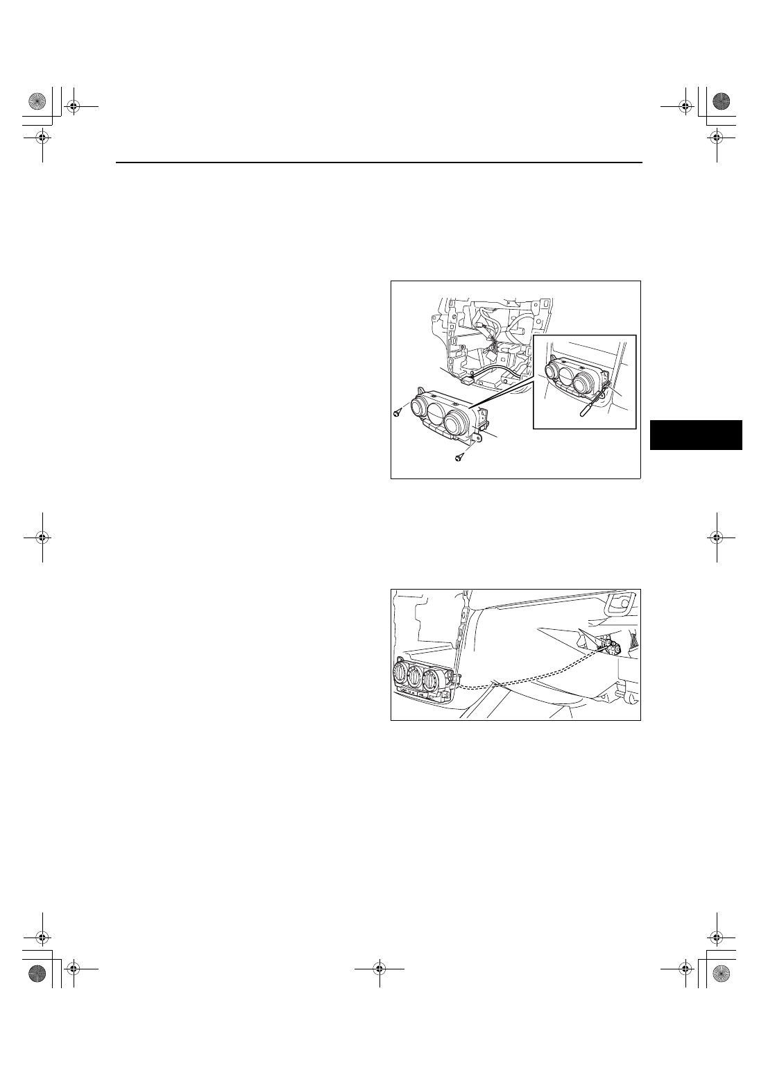
3. Remove the screws and climate control unit.
4. Release the tab and pull the climate control unit 

toward you.

5. Disconnect the climate control unit connectors 

and remove the climate control unit.

6. Install in the reverse order of removal.

End Of Sie

CLIMATE CONTROL UNIT REMOVAL [MANUAL AIR CONDITIONER]

id074000809100

1. Disconnect the negative battery cable.
2. Remove the following parts:

(1) Glove compartment. (See 09-17-8 GLOVE COMPARTMENT REMOVAL/INSTALLATION.)
(2) Console (See 09-17-13 CONSOLE REMOVAL/INSTALLATION.)
(3) Lower panel (See 09-17-9 LOWER PANEL REMOVAL/INSTALLATION.)
(4) Center panel (See 09-17-8 CENTER PANEL REMOVAL/INSTALLATION.)
(5) Audio unit (See 09-20-4 AUDIO UNIT 

REMOVAL/INSTALLATION.)

3. Disconnect the air mix wire from wire clamp and 

link.

4. Remove the screws and climate control unit.
5. Release the tab and pull the climate control unit 

toward you.

CLIMATE CONTROL UNIT

CLIMATE 
CONTROL 
UNIT 
CONNECTOR

TAB

acxuuw00001616

WIRE CLAMP AND LINK

acxuuw00001592

1871-1U-06B(07-40).fm  25 ページ  2006年3月16日 木曜日 午後4時1分

CONTROL SYSTEM 

07-40–26

6. Disconnect the climate control unit connectors 

and remove the climate control unit.

End Of Sie

CLIMATE CONTROL UNIT INSTALLATION [MANUAL AIR CONDITIONER]

id074000809200

1. Pass air mix wire through the following routes then connect to A/C unit. (Manual air conditioner)

2. Install the following parts:

(1) Climate control unit to the dashboard.
(2) Audio unit (See 09-20-4 AUDIO UNIT REMOVAL/INSTALLATION.)
(3) Center panel (See 09-17-8 CENTER PANEL REMOVAL/INSTALLATION.)
(4) Lower panel (See 09-17-9 LOWER PANEL REMOVAL/INSTALLATION.)
(5) Console (See 09-17-13 CONSOLE REMOVAL/INSTALLATION.)

3. Adjust the air mix wire. (See 07-40-12 CLIMATE CONTROL UNIT WIRE ADJUSTMENT.)
4. Install the globe compartment.

End Of Sie

AIRFLOW VOLUME CONTROL DIAL INSPECTION

id074000809300

1. Remove the climate control unit.
2. Inspect for continuity between the airflow volume control dial terminals using an ohmmeter.

• If not as specified, replace the airflow volume 

control dial.

End Of Sie

TAB

CLIMATE CONTROL UNIT CONNECTOR

CLIMATE CONTROL UNIT

acxuuw00001617

AIR MIX WIRE

AIR MIX WIRE

acxuuw00001593

A

D

F

C

E

A

C

D

E

F

*

0

1

2

3

4

acxuuw00001889

4

3

2

1

0

Switch
position

A

C

D

E

F

: Continuity

Terminal

acxuuw00001888

1871-1U-06B(07-40).fm  26 ページ  2006年3月16日 木曜日 午後4時1分

TECHNICAL DATA 

07-50–1

07-50

07-50

TECHNICAL DATA

HVAC TECHNICAL DATA . . . . . . . . . . . .  07-50–1

End of Toc

WM: HEATER, VENTILATION AND AIR CONDITIONING (HVAC)

HVAC TECHNICAL DATA

id075000800100

End Of Sie

Item

Specification

REFRIGERANT SYSTEM

Refrigerant

Type

R-134a

Regular amount (approx. quantity)

 (g {oz})

500 {17.7}

BASIC SYSTEM

A/C compressor

Lubrication oil

Type

ATMOS GU10

Sealed volume
 (approx. 
quantity)

 (ml {cc, fl oz})

120 {120, 4.06}

CONTROL SYSTEM

A/C compressor

Magnetic clutch clearance

 (mm {in})

0.3— 0.5 {0.012— 0.019}

1871-1U-06B(07-50).fm  1 ページ  2006年3月15日 水曜日 午前11時32分


Content   ..  298  299  300  301   ..