Mazda CX 7. Manual - part 297
CONTROL SYSTEM
07-40–13
07-40
CLIMATE CONTROL UNIT INSPECTION [FULL-AUTO AIR CONDITIONER]
id074000803400
1. Remove the climate control unit. (See 07-40-25 CLIMATE CONTROL UNIT REMOVAL/INSTALLATION [FULL-
AUTO AIR CONDITIONER].)
2. Install the audio unit. (See 09-20-4 AUDIO UNIT REMOVAL/INSTALLATION.)
3. Connect the climate control unit connector.
4. Connect the negative (-) lead of the tester to body ground.
5. Turn the ignition switch to the ON position.
6. By inserting the positive (+) lead of the tester into each climate control unit terminal, measure the voltage
according to the terminal voltage table.
• If there is any malfunction, inspect the parts under “Inspection item (s)”.
— If the parts under “Inspection item (s)” are found to be normal (except for terminal T), replace the
climate control unit.
— For terminal T, first try replacing the power MOS FET. If there is still any malfunction, replace the
climate control unit.
Terminal Voltage Table (Reference)
Term
inal
Signal
name
Connected to
Measurement
condition
Voltage (V)
Inspection item (s)
A
Communicat
ion
— —
—
—
B
Communicat
ion
— —
—
—
C
Sensor GND
• Ambient
temperature
sensor
• Passenger
compartment
temperature
sensor
• Evaporator
temperature
sensor
• Air mix actuator
• Airflow mode
actuator
Under any condition
1.0 or less
• Climate control unit: terminal voltage
(D)
D
GND
Body ground
Under any condition
1.0 or less
• Wiring harness: continuity (Climate
control unit— GND: D— GND)
E
Solar
radiation
sensor input
Solar radiation
sensor
fluorescent light shined
directly on the solar
radiation sensor
0.1—0.45
• Wiring harness: continuity (Climate
control unit—solar radiation sensor: E—
B, J—A)
• Climate control unit: terminal voltage (J)
• Solar radiation sensor
Blocking light to solar
radiation sensor
0.1 or less
F
Evaporator
temperature
sensor input
Evaporator
temperature sensor
Compared with
temperature detected
by evaporator
temperature sensor
Refer to
graph 3
• Wiring harness: continuity (Climate
control unit—evaporator temperature
sensor: F—B, C—A)
• Wiring harness: short circuit (Climate
control unit—evaporator temperature
sensor: F—B)
• Evaporator temperature sensor
• Climate control unit: terminal voltage (D,
M)
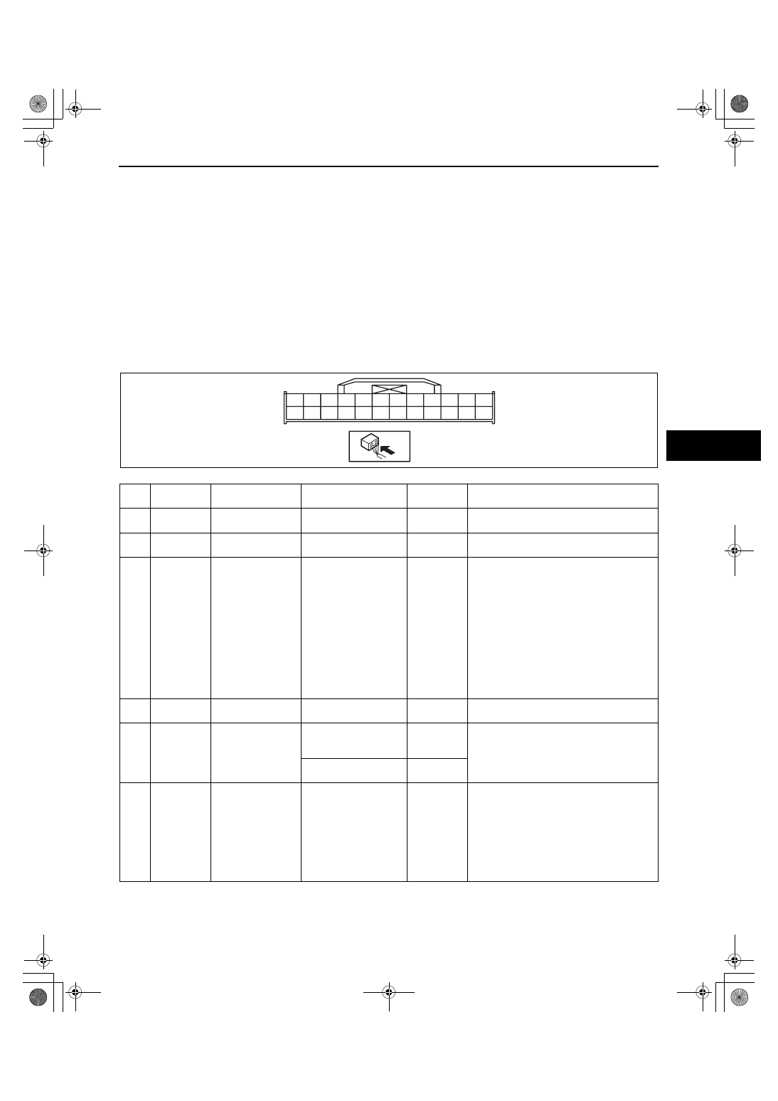
D
F
J
L
M
N
O
P
Q
R
S
T
U
V
A
B
W
X
C
E
G
H
I
K
acxuuw00000985
1871-1U-06B(07-40).fm 13 ページ 2006年3月16日 木曜日 午後4時1分