Mazda CX 7. Manual - part 194


  Index      Mazda     Mazda CX 7 - service repair manual 2007 year


Search            


Content   ..  192  193  194  195   ..


Mazda CX 7. Manual - part 194


ALL WHEEL DRIVE (AWD) 

03-19–7

03-19

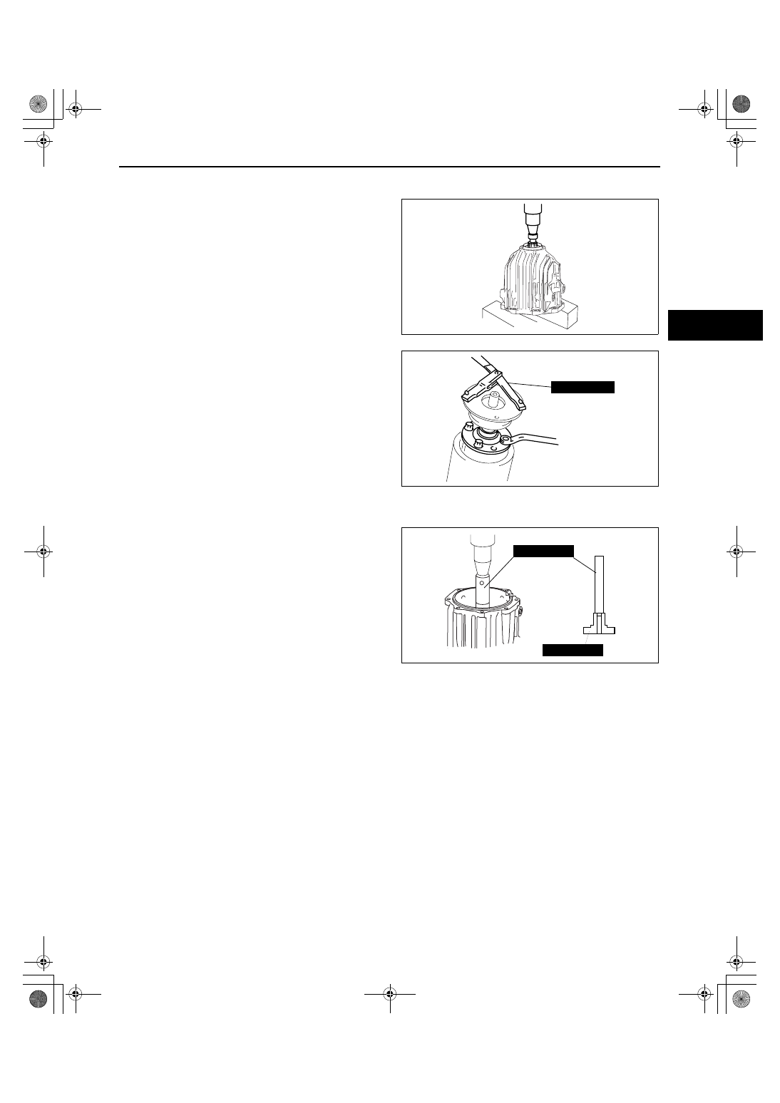
Output Shaft Disassembly Note

1. Remove the coupling unit from the SST.
2. Install the coupling unit to the press as shown, 

and remove the output shaft together with the 
coupling unit.

3. Install the companion flange to the output shaft.

4. Secure the companion flange using the SST, and 

remove the bolts.

5. Remove the output shaft.

Bearing Disassembly Note

1. Remove the bearing using the SSTs and a press.

Substitution SST

• 49 S033 108

Outer diameter: 33— 55 mm {1.30— 2.16 in}
Height: 155 mm {6.10 in} or more

End Of Sie

acxuuw00001448

49 S120 710

acxuuw00001449

49 M005 797

49 S033 108

acxuuw00001450

1871-1U-06B(03-19).fm  7 ページ  2006年3月15日 水曜日 午前11時9分

ALL WHEEL DRIVE (AWD) 

03-19–8

COUPLING COMPONENT ASSEMBLY

id031900800600

Warning

• The engine stand is equipped with a self-lock mechanism, however, if the coupling unit is in a 

tilted condition, the self-lock mechanism could become inoperative. If the coupling unit 
unexpectedly rotates it could cause injury, therefore do not maintain the coupling unit in a tilted 
condition. When turning the coupling unit, grasp the rotation handle firmly.

.

9

8

7

5

4

3

1

2

10

6

SST

SST

R

SST

SST

SST

R

OIL

41.2—53.9
{4.2—5.4, 30.4—39.7} 

167—226
{17.1—23.0,
124—166}

N·m {kgf·m, ft·lbf}

acxuuw00001451

1

Coupling unit

2

Output shaft
(See 03-19-9 Output Shaft Assembly Note)

3

Bearing
(See 03-19-9 Bearing Assembly Note)

4

Snap ring

5

Coupling case
(See 03-19-9 Coupling Case Assembly Note)

6

Shim

7

Oil  seal
(See 03-19-9 Oil Seal Assembly Note)

8

Companion flange
(See 03-19-10 Companion Flange Assembly Note)

9

Washer

10

Locknut
(See 03-19-10 Locknut Assembly Note)

1871-1U-06B(03-19).fm  8 ページ  2006年3月15日 水曜日 午前11時9分

ALL WHEEL DRIVE (AWD) 

03-19–9

03-19

Output Shaft Assembly Note

1. Install the output shaft to the coupling unit and partially tighten the bolts.
2. Install the companion flange to the output shaft.
3. Secure the companion flange using the SST, and 

tighten the bolts.

Tightening torque

41.2— 53.9 N·m {4.2— 5.4 kgf·m, 30.4— 39.7 

ft·lbf}

Bearing Assembly Note

1. Assemble the bearing to the coupling case using 

the SSTs.
Substitution SST

• 49 G030 796

Outer diameter: 58— 61 mm {2.29— 2.40 in}

Coupling Case Assembly Note

Caution

• The coupling unit will be damaged if it is pressed directly by a press. Always press the coupling 

unit into the coupling case using the SST.

1. Assemble the coupling unit to the coupling case 

using the SSTs and a press.
Substitution SST

• 49 S032 333

Outer diameter: 34.2— 40.0 mm {1.35— 1.57 
in}
Inner diameter: 30.2— 32.2 mm {1.19— 1.26 
in}
Inner depth: 65.2 mm {2.57 in} or more

Oil Seal Assembly Note

1. Apply the specified oil to a new oil seal lip.
2. Install the oil seal to the coupling case using the 

SST.
Substitution SST

• 49 W011 102

Outer diameter: 66 mm {2.60 in} or more
Inner diameter: 54— 60 mm {2.13— 2.36 in}
Inner depth: 17.5 mm {0.69 in} or more

49 S120 710

acxuuw00001452

49 G030 797

49 G030 796

acxuuw00001453

49 S032 333

49 W010 107A

acxuuw00001454

49 W011 102

acxuuw00001455

1871-1U-06B(03-19).fm  9 ページ  2006年3月15日 水曜日 午前11時9分

ALL WHEEL DRIVE (AWD) 

03-19–10

Companion Flange Assembly Note

1. Install the coupling case to the SSTs as shown.
2. Install the companion flange.

Locknut Assembly Note

1. Secure the companion flange using the SST, and 

tighten a new locknut.

Tightening torque

167— 226 N·m {17.1— 23.0 kgf·m, 124— 166 

ft·lbf}

End Of Sie

WM: DIFFERENTIAL OIL TEMPERATURE SENSOR

DIFFERENTIAL OIL TEMPERATURE SENSOR INSPECTION

id031900800700

Warning

• Hot differential oil may cause severe burns. Do not perform maintenance while differential oil is 

hot.

1. Disconnect the negative battery cable.
2. Disconnect the differential oil temperature sensor connector and remove the differential oil temperature sensor.
3. Wrap the differential oil temperature sensor with 

plastic wrap and immerse it into a beaker filled 
with water. Gradually raise the water temperature, 
and measure resistance between differential oil 
temperature sensor terminals A and B.

• If not as specified, inspect the harness for 

continuity. If there is normal continuity 
between the terminals, replace the differential 
oil temperature sensor.

Differential oil temperature sensor specification

4. Install the differential oil temperature sensor and connect the connector.
5. Connect the negative battery cable.

49 L027 0A2

acxuuw00002358

49 S120 710

acxuuw00001457

A

B

acxuuw00001458

Water temperature (

°C {°F})

Resistance (kirohm)

0 {32}

91— 100

10 {50}

56— 61

20 {68}

35— 39

30 {86}

23— 25

40 {104}

14— 17

50 {122}

10— 11

60 {140}

7.1— 7.9

70 {158}

5.0— 5.6

80 {176}

3.6— 4.0

1871-1U-06B(03-19).fm  10 ページ  2006年3月15日 水曜日 午前11時9分


Content   ..  192  193  194  195   ..