Mazda CX 7. Manual - part 22
ON-BOARD DIAGNOSTIC [L3 WITH TC]
01-02–43
01-02
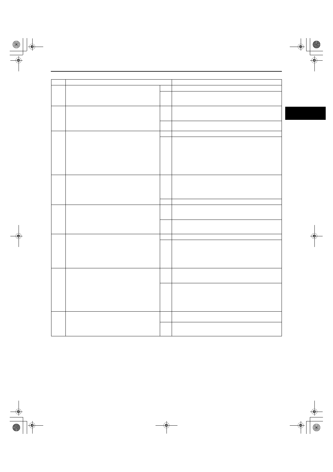
Diagnostic procedure
End Of Sie
STEP
INSPECTION
ACTION
1
VERIFY FREEZE FRAME DATA HAS BEEN
RECORDED
• Has the FREEZE FRAME DATA been
recorded?
Yes
Go to the next step.
No
Record FREEZE FRAME DATA on the repair order, then go
to the next step.
2
VERIFY RELATED REPAIR INFORMATION
AVAILABILITY
• Check for related Service Bulletins and/or on-
line repair information availability.
• Is any related repair information available?
Yes
Perform the repair or diagnosis according to the available
repair information.
• If the vehicle is not repaired, go to the next step.
No
Go to the next step.
3
INSPECT MAP/BOOST AIR TEMPERATURE
SENSOR CONNECTOR FOR POOR
CONNECTION
• Turn the ignition switch off.
• Disconnect the MAP/boost air temperature
sensor connector.
• Inspect for poor connection (damaged, pulled-
out pins, corrosion, etc.).
• Is there any malfunction?
Yes
Repair or replace the terminal, then go to Step 7.
No
Go to the next step.
4
INSPECT BOOST AIR TEMPERATURE SENSOR
• Inspect the boost air temperature sensor.
(See01-40-31 BOOST AIR TEMPERATURE
SENSOR INSPECTION[L3 WITH TC].)
• Is there any malfunction?
Yes
Replace the MAP/boost air temperature sensor, then go to
Step 7.
(See01-40-29 MANIFOLD ABSOLUTE PRESSURE (MAP)
SENSOR/BOOST AIR TEMPERATURE SENSOR
REMOVAL/INSTALLATION[L3 WITH TC].)
No
Go to the next step.
5
INSPECT ECT SENSOR
• Inspect the ECT sensor.
(See01-40-25 ENGINE COOLANT
TEMPERATURE (ECT) SENSOR
INSPECTION[L3 WITH TC].)
• Is there any malfunction?
Yes
Replace the ECT sensor, then go to Step 7.
(See01-40-24 ENGINE COOLANT TEMPERATURE (ECT)
SENSOR REMOVAL/INSTALLATION[L3 WITH TC].)
No
Go to the next step.
6
INSPECT PCM CONNECTOR FOR POOR
CONNECTION
• Turn the ignition switch off.
• Disconnect the PCM connector.
• Inspect for poor connection (damaged, pulled-
out pins, corrosion, etc.).
• Is there any malfunction?
Yes
Repair or replace the terminal, then go to the next step.
No
Go to the next step.
7
VERIFY TROUBLESHOOTING OF DTC P0096
COMPLETED
• Make sure to connect all disconnected
connectors.
• Clear the DTC from the PCM memory using
the M-MDS.
• Start the engine and run it under the FREEZE
FRAME DATA condition.
• Is the same DTC present?
Yes
Replace the PCM, then go to the next step.
(See01-40-6 PCM REMOVAL/INSTALLATION[L3 WITH
TC].)
No
Go to the next step.
8
VERIFY AFTER REPAIR PROCEDURE
• Perform the “AFTER REPAIR PROCEDURE”.
(See01-02-10 AFTER REPAIR
PROCEDURE[L3 WITH TC].)
• Are any DTCs present?
Yes
Go to the applicable DTC inspection.
(See01-02-13 DTC TABLE[L3 WITH TC].)
No
DTC troubleshooting completed.
1871-1U-06B(01-02).fm 43 ページ 2006年3月15日 水曜日 午前10時32分