Mazda 6. Manual - part 331


  Index      Mazda     Mazda 6 - service repair manual 2002 year


Search            


Content   ..  329  330  331  332   ..


Mazda 6. Manual - part 331


T–84

WARNING AND INDICATOR SYSTEM 

OIL PRESSURE SWITCH INSPECTION

A6E811818500W01

1. Verify that the oil pressure warning light illuminates when the ignition switch is at ON position.
2. Verify that the oil pressure warning light goes off when the engine is started.

• If the oil pressure warning light does not illuminate or remains illuminated, inspect the related wiring 

harness.
— If the related wiring harness are normal, inspect the oil pressure. (See 

D–3 OIL PRESSURE 

INSPECTION

.)

• If the oil pressure is normal, replace the oil pressure switch.

End Of Sie

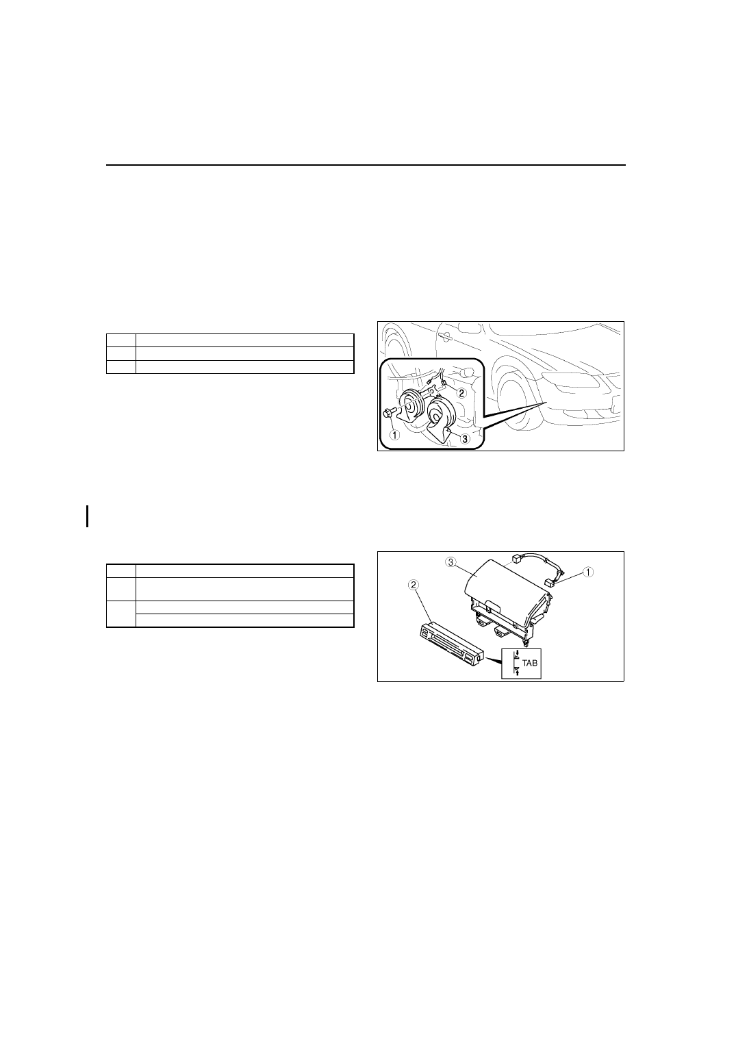
HORN REMOVAL/INSTALLATION

A6E811866790W01

1. Disconnect the negative battery cable.
2. Bend the mud guard.
3. Remove in the order indicated in the table.

4. Install in the reverse order of removal.

End Of Sie

INFORMATION DISPLAY REMOVAL/INSTALLATION

A6E811855000W01

1. Disconnect the negative battery cable.
2. Remove the center panel module. (See 

T–96 CENTER PANEL MODULE REMOVAL/INSTALLATION

.)

3. Remove the LCD unit. (with car-navigation system) (See 

T–98 LCD UNIT REMOVAL/INSTALLATION

.)

4. Remove the center box. (without car-navigation system)
5. Remove in the order indicated in the table.
6. Install in the reverse order of removal.

Information Display Removal Note

1. Squeeze the tabs of information display and pull it forward to it.

End Of Sie

1

Bolt

2

Connector

3

Horn

A6E8118W001

1

Short harness

2

Information display
(See 

T–84 Information Display Removal Note

)

3

LCD unit (with car-navigation system)

Center box (without car-navigation system)

A6E8118W008

THEFT-DETERRENT SYSTEM 

T–85

T

BONNET SWITCH INSPECTION

A6E812001084W01

Note

• Bonnet switch has a built-in bonnet lock.

1. Open the bonnet.
2. Disconnect the negative battery cable.
3. Remove the radiator grille.
4. Disconnect the bonnet switch connector.
5. Check the continuity between the bonnet switch 

terminals A and B using an ohmmeter.

• If there is continuity, replace the bonnet 

switch.

6. Lock the bonnet lock using a flat-head 

screwdriver or equivalent as shown.

7. Check the no continuity between the bonnet 

switch terminals A and B using an ohmmeter.

• If there is no continuity, replace the bonnet 

switch.

Caution

• After the inspection, unlock the bonnet 

lock. If closing the bonnet with the 
bonnet lock locked, the bonnet lock and/
or bonnet striker may be broken.

End Of Sie

THEFT-DETERRENT SYSTEM

A6E8120W002

A6E8120W003

T–86

THEFT-DETERRENT SYSTEM 

THEFT-DETERRENT CONTROL MODULE REMOVAL/INSTALLATION

A6E812067790W01

1. Disconnect the negative battery cable.
2. Remove the center panel module. (See 

T–96 CENTER PANEL MODULE REMOVAL/INSTALLATION

.)

3. Remove in the order indicated in the table.

4. Install in the reverse order of removal.

End Of Sie

THEFT-DETERRENT CONTROL MODULE INSPECTION

A6E812067790W02

1. Remove the theft-deterrent control module without disconnecting the connectors.
2. Measure the voltage at the theft-deterrent control module terminals as indicated below.
3. Disconnect the theft-deterrent control module connector before inspecting for continuity at terminals L, Q, S, T, 

and V.

4. If not as specified, inspect the parts listed under “Action.”

• If the parts and wiring harnesses are okay but the system still does not work properly, replace the 

theft-deterrent control module.

Terminal Voltage Table (Reference)

1

Screw

2

Connector

3

Theft-deterrent control module

A6E8120W001

Terminal

Signal

Connected to

Test condition

Voltage (V)/

continuity

Action

A

B

IG1

METER IG 15 A 
fuse

Ignition switch at ON 
position

B+

• Inspect ignition switch

(See 

T–20 IGNITION 

SWITCH INSPECTION

)

• Inspect METER IG 15 A 

fuse

• Inspect related harness

Ignition switch at 
LOCK or ACC position

Below 1.0

C

Power supply

ROOM 15 A fuse

Under any condition

B+

• Inspect ROOM 15 A fuse

• Inspect related harness

D

E

F

Intruder sensor power 
supply

Intruder sensor

Theft-deterrent system 
pre-arming or arming

B+

• Inspect related harness

Other

Below 1.0

G

Security light on/off

Security light

Security light on

Below 2.0

• Inspect security light

• Inspect related harness

Security light off

B+

H

Hazard warning signal 
output

Flasher unit

Theft-deterrent system 
alarm: Active

Alternates 

between 

below 1.0 

and B+

• Inspect flasher unit

(See 

T–44 FLASHER 

UNIT INSPECTION

)

• Inspect related harness

Theft-deterrent system 
alarm: Other

B+

A6E8120W004

THEFT-DETERRENT SYSTEM 

T–87

T

I

Theft-deterrent siren 
on/off

Theft-deterrent 
siren

Theft-deterrent system 
alarm: Active

Alternates 

between 

below 1.0 

and B+

• Inspect related harness

Theft-deterrent system 
alarm: Other

B+

J

• Theft-deterrent 

system recognition 
signal output

• Keyless entry 

system operation 
signal input

Door lock timer unit Under any condition

B+

• Inspect door lock timer 

unit
(See 

S–34 DOOR LOCK 

TIMER UNIT 
INSPECTION

)

• Inspect related harness

K

Horn on/off

Horn relay

Theft-deterrent system 
alarm: Other

B+

• Inspect horn relay

(See 

T–24 RELAY 

INSPECTION

)

• Inspection related 

harness

Theft-deterrent system 
alarm: Active

Alternates 

between 

below 1.0 

and B+

L

Theft-deterrent control 
module ground

GND

Under any condition: 
inspect for continuity 
to ground

Yes

• Inspect GND

M

Key reminder switch 
on/off

Key reminder 
switch

Key reminder switch 
on (key inserted)

B+

• Inspect key reminder 

switch
(See 

T–21 KEY 

REMINDER SWITCH 
INSPECTION

)

• Inspect related harness

Key reminder switch 
off (key removed)

Below 1.0

N

O

Intruder sensor on/off

Intruder sensor

Theft-deterrent system 
pre-arming or arming

Alternates 

between 

below 1.0 

and B+

• Inspect related harness

P

Q

Bonnet open/closed

Bonnet switch

Bonnet switch on: 
inspect for continuity 
to ground

Yes

• Inspect bonnet switch

(See 

T–85 BONNET 

SWITCH INSPECTION

)

• Inspect related harness

Bonnet switch off: 
inspect for continuity 
to ground

No

R

Trunk compartment 
light switch/cargo 
compartment light 
switch on/off

• Trunk 

compartment 
light switch

• Cargo 

compartment 
light switch

Trunk compartment 
light switch/cargo 
compartment light 
switch on

Below 1.0

• Inspect trunk 

compartment light switch
(See 

T–51 TRUNK 

COMPARTMENT LIGHT 
SWITCH INSPECTION

)

• Inspect cargo 

compartment light switch
(See 

T–50 CARGO 

COMPARTMENT LIGHT 
SWITCH INSPECTION

)

• Inspect related harness

Trunk compartment 
light switch/cargo 
compartment light 
switch off

B+

S

Door open/closed

Door switch

Any door open: 
inspect for continuity 
to ground

Yes

• Inspect door switch

(See 

T–52 DOOR 

SWITCH INSPECTION

)

• Inspect related harness

All doors closed: 
inspect for continuity 
to ground

No

Terminal

Signal

Connected to

Test condition

Voltage (V)/

continuity

Action


Content   ..  329  330  331  332   ..