Mazda 6. Manual - part 309
S–130
TROUBLESHOOTING [KEYLESS ENTRY SYSTEM]
End Of Sie
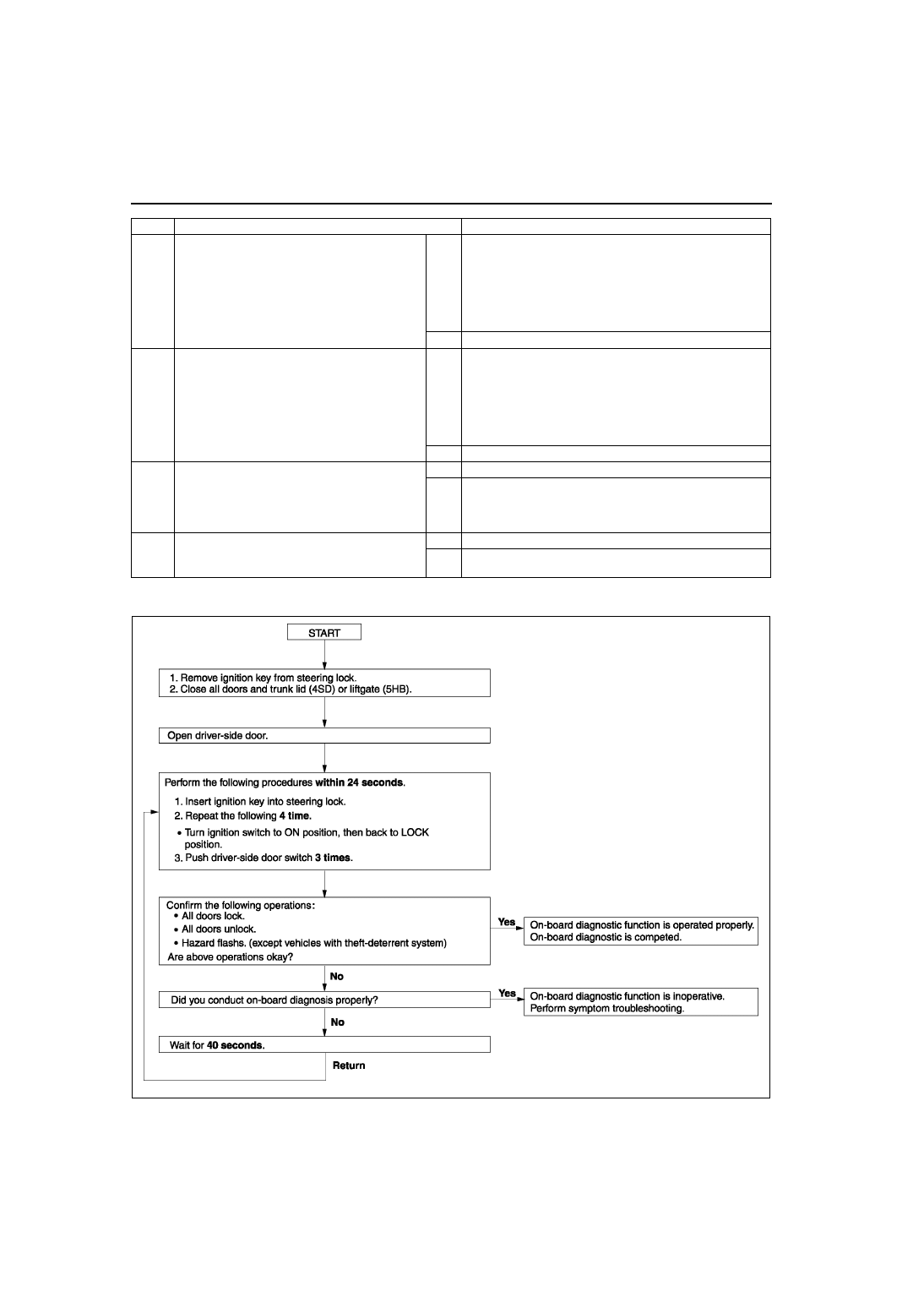
ON-BOARD DIAGNOSTIC FUNCTION
A6E778269000W04
End Of Sie
3
• Did customer use keyless entry system in
particular area, such as being near TV
towers, power plants, power lines, or
factories?
Yes
Attempt to lock/unlock doors with transmitter in
non-interference area.
If system operates:
• Area of operation is bad. Explain effect of outside
interference on transmitter to customer.
If system does not operate:
• Go to next step.
No
Go to next step.
4
• Are any of the following after-market
electrical parts on the vehicle?
— Cellular phone
— Radio-wave equipment
— Remote engine starter
— TV, etc.
Yes
Disconnect after-market electrical part connectors and
attempt to lock/unlock doors with transmitter.
If system operates:
• After-market electrical parts are interfering with keyless
entry system.
If system does not operate:
• Go to next step.
No
Go to next step.
5
• Perform on-board diagnostic function.
• Does on-board diagnostic function work?
Yes
Go to next step.
No
• Go to Step 1 of NO. 1 ONE OR MORE ON-BOARD
DIAGNOSTIC FUNCTIONS INOPERATIVE.
• Go to Step 1 of NO. 2 ALL ON-BOARD DIAGNOSTIC
FUNCTIONS INOPERATIVE.
6
• Attempt to reprogram transmitter ID code.
• Can transmitter ID code be reprogrammed?
Yes
System is normal now.
No
Go to Step 1 of troubleshooting NO. 3 TRANSMITTER ID
CODE CANNOT BE REPROGRAMMED.
STEP
INSPECTION
ACTION
A6E7782W003