Mazda 6. Manual - part 245


  Index      Mazda     Mazda 6 - service repair manual 2002 year


Search            


Content   ..  243  244  245  246   ..


Mazda 6. Manual - part 245


P–36

DYNAMIC STABILITY CONTROL 

Pressure reduction

Note

• To protect the DSC HU/CM, the solenoid valve used for simulations and the ABS motor stay on for 10 

seconds each time they are switched on.

4. Send the command while pressing on the brake pedal and attempting to rotate the wheel being inspected.
5. When pressure is being maintained, and a click sound indicating the solenoid is operating comes from the DSC 

HU/CM, confirm that the wheel does not rotate. When pressure is being reduced, and a click sound indicating 
the solenoid is operating comes from DSC HU/CM, confirm that the wheel rotates, even though the brake pedal 
is being depressed.

• Performing the inspections above determines the following.

— The DSC HU/CM brake lines are normal
— The DSC HU/CM hydraulic system is not significantly abnormal
— The DSC HU/CM wiring is normal
— Output system harness in DSC HU/CM (solenoid, relay) are normal

• However, the following items cannot be checked.

— The DSC HU/CM input system harness and parts
— Extremely small leaks in the DSC HU/CM internal hydraulic system
— Unusual intermittent occurrences in the above items

DSC Control Inspection

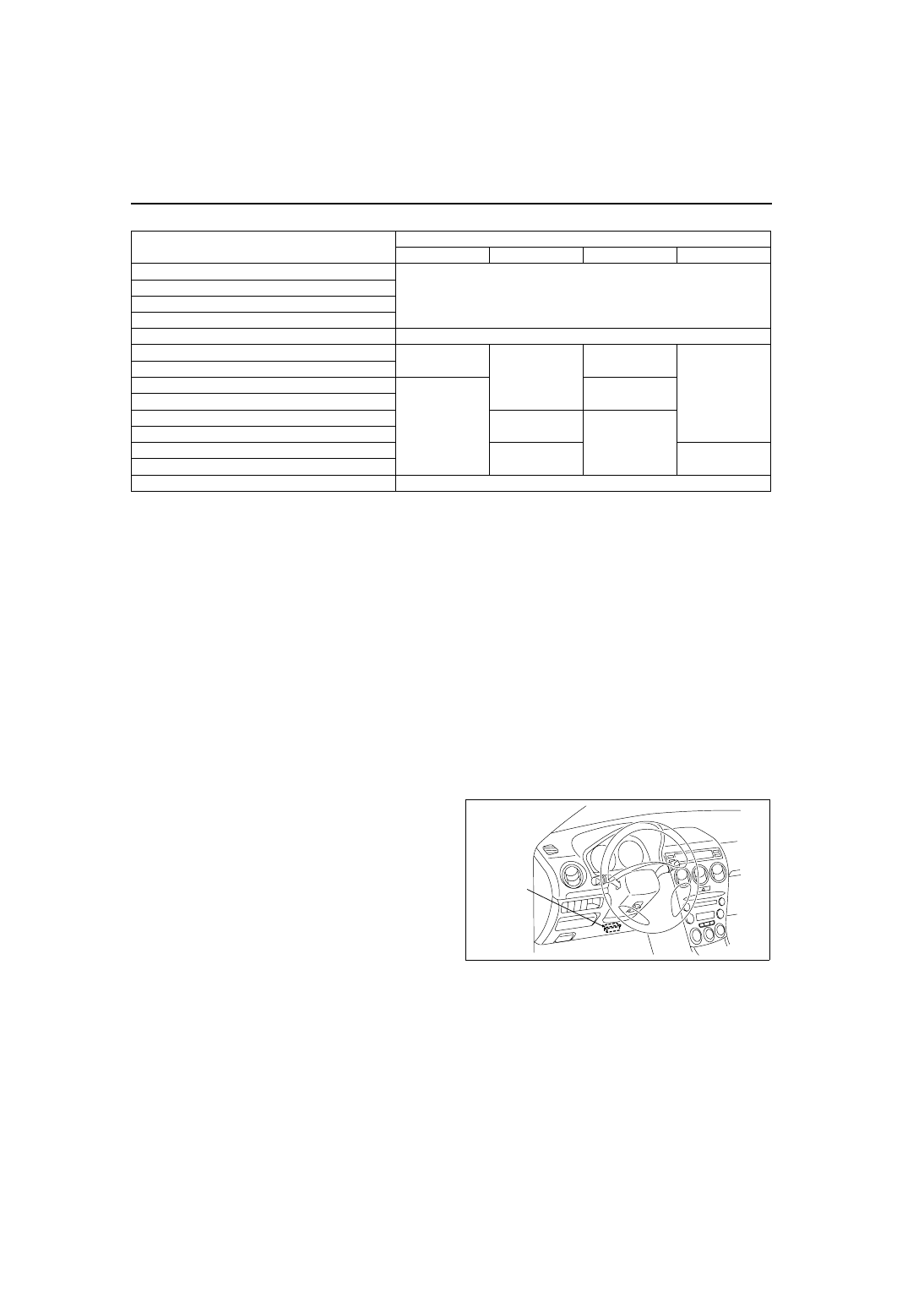
1. Perform the “Preparation.”
2. Connect WDS or equivalent to the DLC-2.
3. Set up an active command modes inspection 

according to the combination of commands 
below.

Command name

Wheels

LF

RF

LR

RR

LF_TC_VLV

OFF

RF_TC_VLV

LF_DSC_V

RF_DSC_V

ABS_POWER

ON

LF_INLET

ON

OFF

OFF

OFF

LF_OUTLET

LR_INLET

OFF

ON

LR_OUTLET

RF_INLET

ON

OFF

RF_OUTLET

RR_INLET

OFF

ON

RR_OUTLET

PMP_MOTOR

ON

DLC-2

A6E3970W002

DYNAMIC STABILITY CONTROL 

P–37

P

Pressure retention

Note

• To protect the DSC HU/CM, the solenoid valve used for simulations and the ABS motor stay on for 10 

seconds each time they are switched on.

4. Send the command while attempting to rotate the wheel being inspected.
5. When pressure is being maintained, and a click sound indicating the solenoid is operating comes from the DSC 

HU/CM, confirm that the wheel does not rotate.

• Performing the inspections above determines the following.

— The DSC HU/CM brake lines are normal
— The DSC HU/CM hydraulic system is not significantly abnormal
— The DSC HU/CM wiring is normal
— Output system harness in DSC HU/CM (solenoid, relay) are normal

• However, the following items cannot be checked.

— The DSC HU/CM input system harness and parts
— Extremely small leaks in the DSC HU/CM internal hydraulic system
— Unusual intermittent occurrences in the above items

End Of Sie

Command name

Wheels

Inhibition of understeer tendency 

control

Inhibition of oversteer tendency 

control

LF

RF

LR

RR

LF_TC_VLV

ON

OFF

ON

RF_TC_VLV

OFF

ON

OFF

LF_DSC_V

OFF

RF_DSC_V

ABS_POWER

ON

LF_INLET

OFF

OFF

OFF

ON

LF_OUTLET

OFF

LR_INLET

ON

LR_OUTLET

OFF

RF_INLET

ON

RF_OUTLET

OFF

RR_INLET

ON

RR_OUTLET

OFF

PMP_MOTOR

ON

P–38

DYNAMIC STABILITY CONTROL 

DSC HU/CM REMOVAL/INSTALLATION

A6E692067650W03

Caution

• When replacing the DSC HU/CM, configuration procedure must be done before removing the DSC 

HU/CM. If configuration is not completed before removing the DSC HU/CM, DTC B2477 will be 
detected.

• Do not drop the DSC HU/CM. Replace it if it is subjected to an impact.

1. Configurate the DSC HU/CM (when only replacing it).(See 

P–29 ABS (ABS/TCS) or DSC HU/CM 

CONFIGURATION

.)

2. Remove the battery, battery tray and battery tray bracket.(See 

G–3 BATTERY REMOVAL/INSTALLATION

.)

3. Remove the under cover.
4. Remove in the order indicated in the table.
5. Install in the reverse order of removal.

.

A6E6920W001

1

Connector
(See 

P–39 Connector Removal Note

)

(See 

P–39 Connector Installation Note

)

2

Brake pipe

3

DSC HU/CM and Bracket
(See 

P–39 DSC HU/CM and Bracket Removal/

Installation Note

)

4

Bracket

5

DSC HU/CM 

DYNAMIC STABILITY CONTROL 

P–39

P

Connector Removal Note

1. Rotate the lock lever 40

° to the direction A, then 

push the lock lever to the direction B.

Caution

• After rotated the lever 40° , do not push 

the lock lever to the direction C. The lock 
lever will be damaged.

2. Verify that the lock lever is completely returned.
3. Remove the harness side connector to the 

direction D.

DSC HU/CM and Bracket Removal/Installation Note

1. When removing/installing the DSC HU/CM from/to the vehicle, attach a strip of tape on the DSC HU/CM 

connector to prevent brake fluid from entering.

Connector Installation Note

1. Verify that the connection part and waterproof packing are free of foreign material, then connect the connector.
2. Verify that the lock lever is completely pushed in.

End Of Sie

A6E6920W011

A6E6916W005


Content   ..  243  244  245  246   ..