Mazda 6. Manual - part 95
UNITS
GI–11
GI
UNITS
A6E201200002W01
Conversion to SI Units (Système International d'Unités)
• All numerical values in this manual are based on SI units. Numbers shown in conventional units are converted
from these values.
Rounding Off
• Converted values are rounded off to the same number of places as the SI unit value. For example, if the SI unit
value is 17.2 and the value after conversion is 37.84, the converted value will be rounded off to 37.8.
Upper and Lower Limits
• When the data indicates upper and lower limits, the converted values are rounded down if the SI unit value is
an upper limit and rounded up if the SI unit value is a lower limit. Therefore, converted values for the same SI
unit value may differ after conversion. For example, consider 2.7 kgf/cm
2
in the following specifications:
210—260 kPa {2.1—2.7 kgf/cm
2
, 30—38 psi}
270—310 kPa {2.7—3.2 kgf/cm
2
, 39—45 psi}
• The actual converted values for 2.7 kgf/cm
2
are 264 kPa and 38.4 psi. In the first specification, 2.7 is used as
an upper limit, so the converted values are rounded down to 260 and 38. In the second specification, 2.7 is
used as a lower limit, so the converted values are rounded up to 270 and 39.
End Of Sie
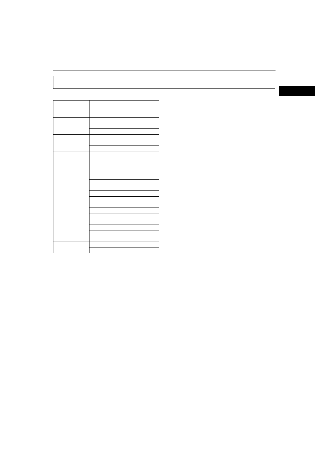
UNITS
Electrical current
A (ampere)
Electric power
W (watt)
Electric resistance
Ω (ohm)
Electric voltage
V (volt)
Length
mm (millimeter)
in (inch)
Negative pressure
kPa (kilo pascal)
mmHg (millimeters of mercury)
inHg (inches of mercury)
Positive pressure
kPa (kilo pascal)
kgf/cm
2
(kilogram force per square
centimeter)
psi (pounds per square inch)
Torque
N·m (Newton meter)
kgf·m (kilogram force meter)
kgf·cm (kilogram force centimeter)
ft·lbf (foot pound force)
in·lbf (inch pound force)
Volume
L (liter)
US qt (U.S. quart)
Imp qt (Imperial quart)
ml (milliliter)
cc (cubic centimeter)
cu in (cubic inch)
fl oz (fluid ounce)
Weight
g (gram)
oz (ounce)