Mazda 6. Manual - part 67


  Index      Mazda     Mazda 6 - service repair manual 2002 year


Search            


Content   ..  65  66  67  68   ..


Mazda 6. Manual - part 67


T–44

THEFT-DETERRENT SYSTEM 

End Of Sie

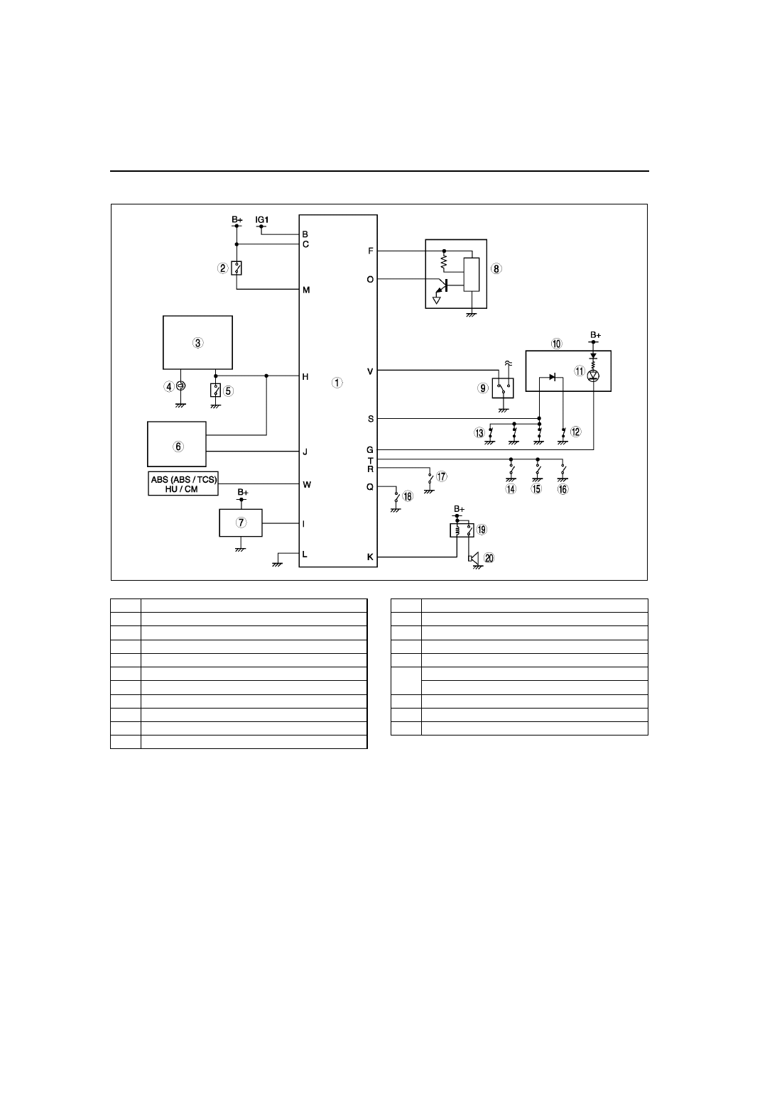
SYSTEM WIRING DIAGRAM

A6E812050000T03

.

End Of Sie

A6E8120T001

1

Theft-deterrent control module

2

Key reminder switch

3

Flasher unit

4

Turn light

5

Hazard warning switch

6

Door lock timer unit

7

Theft-deterrent siren

8

Intruder sensor

9

Driver’s door lock-link switch

10

Instrument cluster

11

Security light

12

Door switch (driver’s side)

13

Door switch (except driver’s side)

14

Passenger’s door lock-link switch

15

Rear door lock-link switch (right)

16

Rear door lock-link switch (left)

17

Trunk compartment light switch (4SD)

Cargo compartment light switch (5HB)

18

Bonnet switch

19

Horn relay

20

Horn

THEFT-DETERRENT SYSTEM 

T–45

T

T

SYSTEM FLOWCHART

A6E812050000T04

End Of Sie

A6E8120T007

T–46

THEFT-DETERRENT SYSTEM 

THEFT-DETERRENT SIREN

A6E812050000T05

The theft-deterrent siren is located on the rear, left side of the trunk lid (4SD) or liftgate (5HB).

Controlled by the following vehicle conditions:
— Standard alert control
— Open circuit alert control

Standard Alert Control

The siren beeps when receiving an alert initialization signal from the theft-deterrent control module. When a go-
to-initial signal is received the siren is stopped.

Open Circuit Alert Control

A back-up power supply is integrated in the theft-deterrent siren.

When an open circuit is detected in the related wiring harness, the theft-deterrent siren beeps using the back-
up power supply.

If any one of the following conditions are met, the siren is stopped:
— Detects that all related wiring harness are properly connected.
— Receives go-to-initial signal from the theft-deterrent control module.

End Of Sie

A6E8120T004

1

Theft-deterrent control module

2

Theft-deterrent siren

3

Alert initialization signal

4

Siren beeps

A6E8120T005

1

Theft-deterrent control module

2

Theft-deterrent siren

3

Siren beeps

4

Siren stops

5

Approx. 30 seconds

6

Approx. 5 seconds

7

Maximum 9 cycles

THEFT-DETERRENT SYSTEM 

T–47

T

T

INTRUDER SENSOR

A6E812050000T06

Outline

The intruder sensor is located in center part of the roof on sliding sunroof-equipped vehicles or the forward part 
of the roof on sliding sunroof non-equipped vehicles.

The intruder sensor detects movement in the vehicle by radio waves and sends the detection signal to the 
theft-deterrent control module.

An intruder sensor cut-off switch has been installed on the keyless entry system transmitter. If the intruder 
sensor cut-off switch is on while the theft-deterrent system is pre-armed, intruder sensor radio wave output is 
cut, and movement detection is stopped.

.

Operation

1. When the theft-deterrent system is armed, the intruder sensor outputs a 2.45 GHz radio wave in the passenger 

compartment. The intruder sensor detects phase differences in radio waves (reflected waves) that are output 
and bounced off a target object. 

2. When a phase difference in reflected waves occurs by movement in the vehicle (intruder), the CPU calculates 

the level of phase difference.

3. If the level of phase difference is higher than specified, the intruder sensor sends a detection signal to the theft-

deterrent module.

.

A6E8120T003

1

Intruder sensor (without sliding sunroof)

2

Intruder sensor (with sliding sunroof)

3

Transmitter

4

Intruder sensor cut-off switch

A6E8120T006

1

Target object

2

Receiver

3

Transmitter

4

Phase detection area

5

Oscillator

6

CPU

7

Detection signal output

8

Theft-deterrent control module


Content   ..  65  66  67  68   ..