Mazda Protege 5. Manual - part 210


  Index      Mazda     Mazda Protege 5 - service repair manual 2002 year


Search            


Content   ..  208  209  210  211   ..


Mazda Protege 5. Manual - part 210


CONVENTIONAL BRAKE SYSTEM 

04–11–9

04–11

3. Invert the SST used in Step 1 and place it on the 

power brake unit.

4. Measure the clearance between the end of the 

SST and the push rod of the power brake unit.

If it is not 0.1—0.4 mm {0.004—0.016 in}
loosen the push rod locknut and turn the push 
rod to adjust it using the SSTs.

End Of Sie

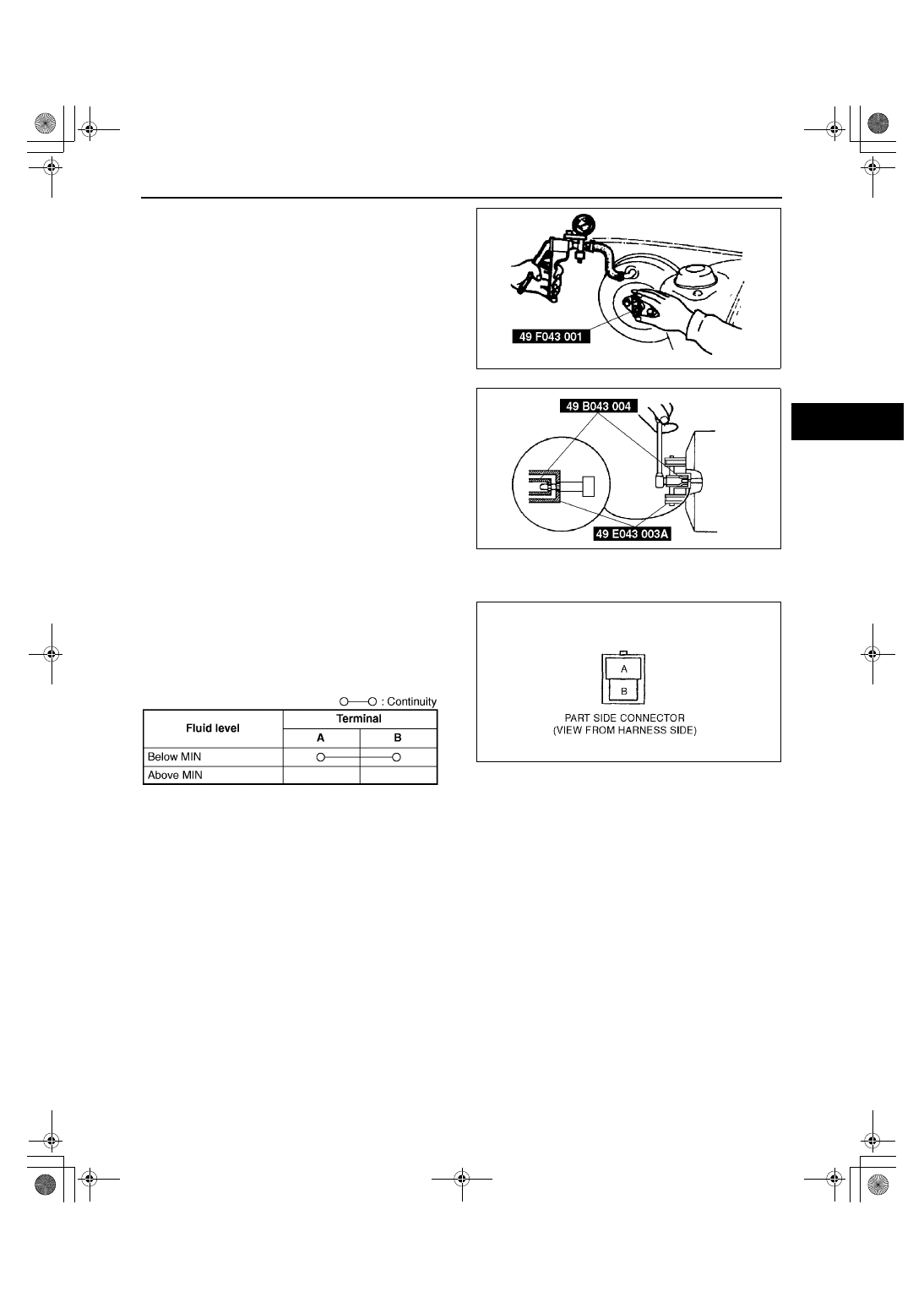
FLUID LEVEL SENSOR INSPECTION

A3U041143540W01

1. Disconnect the sensor connector.
2. Connect an ohmmeter to the connector.
3. Starting with the fluid level above MIN, verify that 

there is no continuity.

4. Remove the brake fluid and verify that there is 

continuity when the level is below MIN.

If not as specified, replace the sensor.

End Of Sie

X3U411WAB

X3U411WAC

Y3U411WA1

X3U411WAD

1712-1U-01G(04-11).fm  9 ページ  2001年6月29日 金曜日 午前10時3分

CONVENTIONAL BRAKE SYSTEM 

04–11–10

MASTER CYLINDER DISASSEMBLY/ASSEMBLY

A3U041143400W02

Caution

••••

If the master cylinder body is damaged, replace the unit as an assembly. When securing the 
master cylinder in a vise, tighten only the flange of the master cylinder.

1. Disassemble in the order indicated in the table.
2. Assemble in the reverse order of disassembly.

.

Z3U0411W011

1

Cap  set

2

Float

3

Screw

4

Reservoir

5

Joint bushing

6

Fluid level sensor

7

Snap ring

8

Spacer

9

Piston guide

10

O-ring

11

Cup

12

Primary piston stopper

13

Primary piston

14

Stop screw and O-ring (without ABS)
(See04–11–11 Stop Screw and O-ring (without 
ABS) Assembly Note)

15

Stop pin and O-ring (with ABS)
(See 04–11–11 Stop Pin and O-ring (with ABS) 
Assembly Note)

16

Secondary piston

17

Master cylinder body

1712-1U-01G(04-11).fm  10 ページ  2001年6月29日 金曜日 午前10時3分

CONVENTIONAL BRAKE SYSTEM 

04–11–11

04–11

Stop Screw and O-ring (without ABS) Assembly Note

1. Install the secondary piston and primary piston.
2. Install the new O-ring onto the stop screw.
3. Push the primary piston assembly in full.
4. Install and tighten the stop screw.

Tightening torque

2.0—2.4 N·m {20—25 kgf·cm, 18—21 in·lbf}

5. Push and release the secondary piston 

component to verify that it is held properly by the 
stop screw.

Stop Pin and O-ring (with ABS) Assembly Note

1. Install the secondary piston with the piston hole facing the stop pin and primary piston.
2. Install the new O-ring onto the stop pin.
3. Push the primary piston assembly in full.
4. Install and tighten the stop pin.

Tightening torque

6.87—9.80 N·m {70—100 kgf·cm, 60.8—86.7 in·lbf}

5. Push and release the secondary piston 

component to verify that it is held properly by the 
stop pin.

End Of Sie

POWER BRAKE UNIT INSPECTION

A3U041143800W01

Power Brake Unit Function Check
Simple method

Note

Replace power brake unit component if necessary.

Step 1

1. With engine stopped, depress the pedal a few times.
2. With pedal depressed, start the engine.

If the pedal moves down slightly, immediately after engine starts, the unit is operating.

If not as specified, inspect for damage on the check valve or vacuum hose, and examine the installation. 
Repair if necessary, and inspect it again.

Step 2

1. Start the engine.
2. Stop the engine after it has run for 1 or 2 minutes.
3. Depress the pedal with usual force.

If the first pedal stroke is long and becomes shorter with subsequent strokes, the unit is operating.

If not as specified, inspect for damage on the check valve or vacuum hose, and examine the installation. 
Repair if necessary, and inspect it again.

X3U411WAG

X3U411WAH

1712-1U-01G(04-11).fm  11 ページ  2001年6月29日 金曜日 午前10時3分

CONVENTIONAL BRAKE SYSTEM 

04–11–12

Step 3

1. Start the engine.
2. Depress the pedal with usual force.
3. Stop the engine with the pedal held depressed.
4. Hold the pedal down for about 30 seconds.

If the pedal height does not change, the unit is operating.

If not as specified, inspect for damage on the check valve or vacuum hose, and examine the installation. 
Repair if necessary, and inspect it again.

Inspection using the testers

1. Connect the SSTs, vacuum gauge, and pedal 

depression force gauge as shown in the figure.

Note

Use commercially available gauges and 
pedal depression force gauge.

Bleed the air from the SST at gauge A.

2. After bleeding the air from the SST, conduct the 

test as described in the following steps.

Checking for vacuum loss
(unloaded condition)

1. Start the engine.
2. Stop the engine when the vacuum gauge reading reaches 66.7 kPa {500 mmHg, 19.7 inHg}.
3. Observe the vacuum gauge for 15 seconds.

If the gauge shows 63.4—66.6 kPa {475—500 mmHg, 18.8—19.6 inHg}, the unit is operating.

If a problem is found, inspect for damage on the check valve or vacuum hose, and examine the installation. 
Repair if necessary, and inspect it again.

(loaded condition)

1. Start the engine.
2. Depress the brake pedal with a force of 200 N {20 kgf, 44 lbf}.
3. With the brake pedal depressed, stop the engine when the vacuum gauge reading reaches 66.7 kPa {500 

mmHg, 19.7 inHg}.

4. Observe the vacuum gauge for 15 seconds.

If the gauge shows 63.4—66.6 kPa {475—500 mmHg, 18.8—19.6 inHg}, the unit is operating.

If a problem is found, inspect for damage on the check valve or vacuum hose, and examine the installation. 
Repair if necessary, and inspect it again.

Checking for hydraulic pressure

1. When the engine is stopped (vacuum 0 kPa {0 mmHg, 0 inHg}) and the fluid pressure is within the 

specification, the unit is operating.

2. Start the engine. Depress the brake pedal when the vacuum reaches 66.7 kPa {500 mmHg, 19.7 inHg}.

If the fluid pressure is within the specification, the unit is operating.

If the fluid pressure is not as specified, inspect for damage on the check valve or vacuum hose, and fluid 
leakage of the hydraulic line. Repair as necessary, and inspect again.

End Of Sie

A3U0411W002

Engine type

Pedal force

Fluid pressure

ZM

200 N {20 kgf, 44 lbf}

650 kPa {7 kgf/cm

2

, 94 psi} min.

FS

600 kPa {6 kgf/cm

2

, 87 psi} min.

Engine type

Pedal force

Fluid pressure

ZM

200 N {20 kgf, 44 lbf}

6,500 kPa {66 kgf/cm

2

, 943 psi} min.

FS

7,200 kPa {73 kgf/cm

2

, 1,044 psi} min.

1712-1U-01G(04-11).fm  12 ページ  2001年6月29日 金曜日 午前10時3分


Content   ..  208  209  210  211   ..