Mazda Protege 5. Manual - part 206
SYMPTOM TROUBLESHOOTING
04–03–7
04–03
End Of Sie
NO.3 BRAKE SYSTEM WARNING LIGHT DOES NOT ILLUMINATE
A3U040343000W07
•
When performing an asterisked (*) troubleshooting inspection, shake the wiring harness and connectors while
performing the inspection to discover whether poor contact points are the cause of any intermittent
malfunctions. If there is a problem, check to make sure connectors, terminals and wiring harness are
connected correctly and undamaged.
Diagnostic procedure
End Of Sie
*3
CHECK TO SEE WHETHER MALFUNCTION
IS IN WIRING HARNESS (SHORT TO
GROUND BETWEEN INSTRUMENT
CLUSTER AND ABS HU/CM) OR
INSTRUMENT CLUSTER (OPEN CIRCUIT OR
SHORT TO GROUND)
•
Is there continuity between instrument
cluster connector (16-pin) terminal 2B and
ground?
Yes
Repair wiring harness between instrument cluster and ABS
HU/CM.
No
Replace instrument cluster (open circuit or short to ground
in ABS HU/CM).
STEP
INSPECTION
ACTION
3
BRAKE system warning light does not illuminate
DESCRIPTION
•
BRAKE system warning light does not illuminate with ignition switch on.
POSSIBLE
CAUSE
•
Open circuit or short to ground in BRAKE system warning light circuit.
STEP
INSPECTION
ACTION
1
CHECK FOR SHORT TO GROUND IN ABS
HU/CM
•
Disconnect ABS HU/CM connector and turn
ignition switch on.
•
Does BRAKE system warning light
illuminate?
Yes
Replace ABS HU/CM (short to ground in ABS HU/CM).
No
Go to next step.
2
INSPECT BRAKE SYSTEM WARNING LIGHT
BULB
•
Remove instrument cluster.
•
Inspect BRAKE system warning light bulb.
•
Is it okay?
Yes
Go to next step.
No
Replace BRAKE system warning light bulb.
*3
CHECK TO SEE WHETHER MALFUNCTION
IS IN WIRING HARNESS (SHORT TO
GROUND BETWEEN INSTRUMENT
CLUSTER AND ABS HU/CM) OR
INSTRUMENT CLUSTER (OPEN OR SHORT
TO GROUND)
•
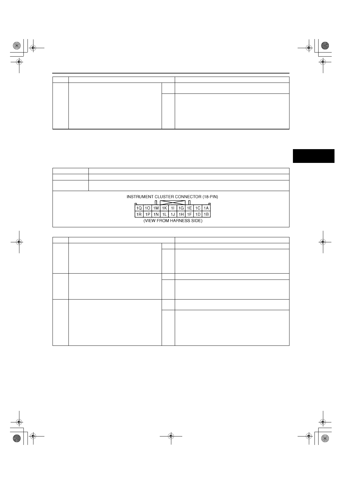
Is there continuity between instrument
cluster connector (18-pin) terminal 1G and
ground?
Yes
Repair wiring harness between instrument cluster and ABS
HU/CM.
No
Replace instrument cluster (open circuit or short to ground
in ABS HU/CM).
1712-1U-01G(04-03).fm 7 ページ 2001年6月29日 金曜日 午前10時2分