Mazda Protege 5. Manual - part 149


  Index      Mazda     Mazda Protege 5 - service repair manual 2002 year


Search            


Content   ..  147  148  149  150   ..


Mazda Protege 5. Manual - part 149


FUEL SYSTEM 

01–14–21

01–14

15. Reconnect the fuel main hose to the fuel main pipe until a click is heard.
16. Pull the quick release connector by hand and verify that it is installed securely.
17. Complete the “AFTER REPAIR PROCEDURE”. (See 01–14–5 AFTER REPAIR PROCEDURE.)

End Of Sie

FUEL FILTER (HIGH-PRESSURE) REMOVAL/INSTALLATION

A3U011434801W01

1. Remove and install the fuel filter (high-pressure). (See 01–14–15 FUEL PUMP UNIT DISASSEMBLY/

ASSEMBLY.)

End Of Sie

FUEL INJECTOR REMOVAL/INSTALLATION

A3U011413250W01

Caution

••••

Disconnecting/connecting the quick release connector without cleaning it may possibly cause 
damage to the fuel pipe and quick release connector. Always clean the quick release connector 
joint area before disconnecting/connecting, and make sure that it is free of foreign material.

1. Complete the “BEFORE REPAIR PROCEDURE”. (See 01–14–4 BEFORE REPAIR PROCEDURE.)
2. Disconnect the battery negative cable.
3. Remove the accelerator cable bracket. (See 01–13A–5 INTAKE-AIR SYSTEM REMOVAL/INSTALLATION 

[ZM].) (See 01–13B–6 INTAKE-AIR SYSTEM REMOVAL/INSTALLATION [FS].)

4. Disconnect the fuel injector connectors and remove the harness from the fuel distributor.
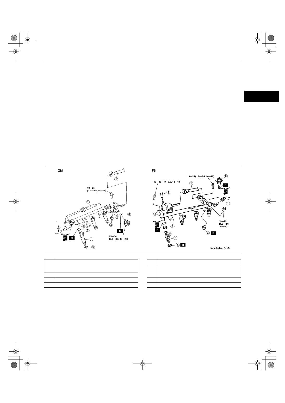
5. Remove in the order indicated in the table.
6. Install in the reverse order of removal.
7. Complete the “AFTER REPAIR PROCEDURE”. (See 01–14–5 AFTER REPAIR PROCEDURE.)

.

Z3U0114W995

1

Plastic fuel hose
(See 01–14–22 Plastic Fuel Hose Removal Note)
(See 01–14–23 Plastic Fuel Hose Installation Note)

2

Vacuum hose

3

Fuel distributor

4

Fuel distributor insulator

5

Fuel injector insulator

6

Fuel injector
(See 01–14–23 Fuel Injector Installation Note (FS 
only))

7

Grommet

8

Pulsation damper

1712-1U-01G(01-14).fm  21 ページ  2001年6月29日 金曜日 午前9時43分

FUEL SYSTEM 

01–14–22

Plastic Fuel Hose Removal Note

Caution

••••

The quick release connector may be damaged when the tab is bent excessively. Do not expand the 
tab over the stopper.

1. Disconnect the quick release connector from the pulsation damper as follows:

(1) Push apart the lock clip and unlock it.

(2) Lift the tab on the blue locking coupler until 

the fuel line can be released.

(3) Pull the fuel hose straight back.

Note

The blue stopper may be removed from the 
quick connector. Take care not to lose it. 
Reinstall it to the quick release connector 
before reconnecting the fuel line.

The orange locking coupler has two internal 
locking tabs which retrain the pulsation 
damper pipe. Be sure that the tab on the 
locking coupler is rotated until it stops to 
release two internal locking tabs.

2. Cover the disconnected quick release connector 

and pulsation damper with vinyl sheet or the like 
to prevent it from being scratched or 
contaminated with foreign materials.

Y3E3912W201

Z3U0114W986

Z3U0114W993

1712-1U-01G(01-14).fm  22 ページ  2001年6月29日 金曜日 午前9時43分

FUEL SYSTEM 

01–14–23

01–14

Plastic Fuel Hose Installation Note

Note

A checker tab is integrated with the quick 
release connector for new plastic fuel hoses. 
The checker tab will be released from the 
quick release connector after it is completely 
engaged with the pulsation damper.

1. Inspect the plastic fuel hose and pulsation 

damper sealing surface for damage and 
deformation, and replace if necessary.

If the quick release connector O-ring is 
damaged or has slipped, replace the plastic 
fuel hose.

2. Apply a small amount of clean engine oil to the 

sealing surface of the pulsation damper.

3. Push the quick release connector straight into the pulsation damper until a click is heard.
4. Lightly pull and push the quick release connector a few times by hand and verify that it can move 2.0—3.0 mm 

{0.08—0.11 in} and it is connected securely.

If quick release connector does not move at all, verify that O-ring is not damaged and slipped, and 
reconnect the quick release connector.

5. Attach the lock clip to the quick release connector 

in the direction of the fuel distributor and lock it, 
as shown in the figure.

Fuel Injector Installation Note (FS only)

1. Install each fuel injector as indicated in the table.

2. Use new fuel injector O-rings.
3. Apply a small amount of engine oil to the O-rings and install them on the fuel distributor.
4. Verify that the O-rings and the fuel injector sealing surfaces are free of foreign material. Clean with gasoline if 

necessary.

5. Align the fuel injector notch with the fuel 

distributor and install the fuel injectors on the fuel 
distributor with a light twisting motion so that the 
O-rings will not be folded.

End Of Sie

YMU114WA8

Y3E3912W202

Cylinder number

Fuel injector body color

No.1, No.2 cylinder

Green

No.3, No.4 cylinder

Purple

X3U114WC6

1712-1U-01G(01-14).fm  23 ページ  2001年6月29日 金曜日 午前9時43分

FUEL SYSTEM 

01–14–24

FUEL INJECTOR INSPECTION

A3U011413250W02

Simulation Test

1. Carry out the “Fuel Injector Operation Inspection”. (See 01–03A–60 Fuel Injector Operation Inspection.) (See 

01–03B–59 Fuel Injector Operation Inspection.)

If not as specified, perform the further inspection for the fuel injectors.

Resistance Inspection

Note

Perform the following test only when directed.

1. Turn the ignition switch off.
2. Disconnect the battery negative cable.
3. Disconnect the fuel injector connectors.
4. Measure the resistance of the fuel injector using an ohmmeter.

If not as specified, replace the fuel injector. (See 01–14–21 FUEL INJECTOR REMOVAL/INSTALLATION.)

If as specified but “Simulation Test” is failed, carry out the “Circuit Open/Short Inspection”.

Resistance [20 

°°°°

C {68 

°°°°

F}]

ZM: Approx.13.8 ohms
FS: 14.2—14.8 ohms 

Circuit Open/Short Inspection

1. Disconnect the PCM connector.
2. Connect the SST (104 Pin Breakout Box) to the 

PCM as shown.

3. Tighten the connector attaching screw.

Tightening torque

7.9—10.7 N·m {80—110 kgf·cm, 69.5—95.4 

in·lbf}

4. Inspect for an open or short circuit in the following 

wiring harnesses by probing the applicable 
sensor and SST (104 Pin Breakout Box) terminals 
with ohmmeter leads.

Y3U114WA9

Y3U114WB8

X3U114WC8

1712-1U-01G(01-14).fm  24 ページ  2001年6月29日 金曜日 午前9時43分


Content   ..  147  148  149  150   ..