Land Rover V8 engine. Manual - part 5


  Index      Land Rover     Land Rover V8 engine (3.5, 3.9, 4.2 Litre) - service repair 1996 year


Search            


Content   ..  3  4  5  6   ..


Land Rover V8 engine. Manual - part 5


ENGINE

6

OVERHAUL

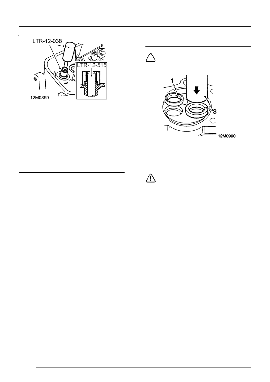
3. Using LRT-12-038 partially press guide into

cylinder head, remove tool.

4. Fit LRT-12-515 over valve guide and continue

to press guide into cylinder head until tool
contacts spring seat. Remove tool.
Valve guide installed height = 24.13 mm

Valve seat insert - inspection

1. Check valve seat inserts for pitting, burning

and wear. Replace inserts as necessary.

Valve seat insert - renew

NOTE: Service valve seat inserts are
available 0.25 mm oversize on outside
diameter to ensure interference fit.

1. Grind a crescent in seat insert, until thin

enough to break using a cold chisel.

CAUTION: Do not damage counterbore.

2. Heat cylinder head evenly to approximately

65

°

C.

3. Using a suitable mandrel, press new insert fully

into counterbore.

4. Allow cylinder head to air cool.

ENGINE

OVERHAUL

7

Valve seats - renew

1. Check condition of valve seats and valves that

are to be reused.

2. Remove carbon from valves and valve seats.

3. Reface valves as necessary. If a valve has to

be ground to a knife-edge to obtain a true seat,
fit a new valve.
Valve seating face angle = 45

°

4. Cut valve seats using LRT-12-501 with

LRT-12-503 and LRT-12-504.
Valve seat:
Width A: Inlet = 37.03 mm

Exhaust = 31.50 mm

Width = 1.5 - 2.00 mm
Angle = 70

°

Angle = 46

° ±

15’

Angle = 20

°

5. Ensure cutter blades are correctly fitted to

cutter head with angled end of blade
downwards, facing work, as illustrated. Check
that cutter blades are adjusted so that middle
of blade contacts area of material to be cut.
Use light pressure and remove only minimum
of material necessary.

ENGINE

8

OVERHAUL

Valves and springs - refit

1. Lap each valve to its seat using fine grinding

paste.

2. Clean valve and seat.

3. Coat valve seat with a small quantity of

engineers blue, insert valve and press it into
position several times without rotating. Remove
valve and check for even and central seating.
Seating position shown by engineers blue
should be in centre of valve face.

4. Check valve installed height if valve seats have

been recut or new valves or valve seat inserts
have been fitted.
Valve installed height = 47.63 mm

5. Thoroughly clean cylinder head, blow out

oilways and coolant passages.

6. Fit new valve stem oil seals, lubricate valve

stems, fit valves, valve springs and caps,
compress valve springs using LRT-12-034 and
fit collets.

7. Using a wooden dowel and mallet, lightly tap

each valve stem two or three times to seat
valve cap and collets.

Cylinder head - refit

1. Clean cylinder block faces using a suitable

release agent and plastic scraper; ensure that
bolt holes in cylinder block are clean and dry.

CAUTION: Do not use metal scraper or
machined surfaces may be damaged.

2.

Engine numbers without suffix B: Thoroughly
clean threads of cylinder head bolts.

CAUTION: Cylinder head bolts - Cylinder
head bolts fitted to engines without suffix
B added to serial number are not

interchangeable with those fitted to engines with
suffix B added to serial number.

3. Fit cylinder head gasket with the word ’TOP’

uppermost.

NOTE: Gasket must be fitted dry.

CAUTION: Engines without suffix B have a
steel gasket whilst engines with suffix B
have a composite gasket. The two types of

gasket are not interchangeable and it is essential
to ensure that the correct type of gasket is fitted.

4. Carefully fit cylinder head and locate on

dowels.

5. Lightly oil threads of cylinder head bolts.

ENGINE

OVERHAUL

9

Engine numbers without suffix B

NOTE: RH cylinder head illustrated

6. Fit cylinder head bolts:

Long bolts: 1, 3 and 5.
Medium bolts: 2, 4, 6, 7, 8, 9, and 10.
Short bolts: 11, 12, 13 and 14.

7. Using sequence shown, progressively tighten

cylinder head bolts to correct torque.

Engine numbers with suffix B

NOTE: RH cylinder head illustrated

8. Fit new cylinder head bolts:

Long bolts: 1, 3 and 5
Short bolts: 2, 4, 6,7, 8, 9 and 10

NOTE: There are no bolts fitted in the four
lower holes in each cylinder head.

9. Using sequence shown, tighten cylinder head

bolts to:
Stage 1 - Correct torque
Stage 2 - 90

°

Stage 3 - Further 90

°

All engines

10. Fit rocker shaft assembly.

TIMING CHAIN AND GEARS

Distributor - remove

1. Remove distributor cap.
2. Rotate crankshaft until centre line of rotor arm

is aligned with No. 1 spark plug segment in
distributor cap and No. 1 piston is at TDC.

3. Scribe an alignment mark between distributor

body and clamp.

4. Remove nut securing distributor clamp.
5. Remove distributor.
6. Remove clamp.
7. Remove and discard ’O’ ring from distributor.


Content   ..  3  4  5  6   ..