Range Rover Classic. Manual - part 121


  Index      Land Rover     Range Rover Classic - service manual 1995 year


Search            


Content   ..  119  120  121  122   ..


Range Rover Classic. Manual - part 121


68

AIR SUSPENSION

12

REPAIR

RESERVOIR PRESSURE SWITCH

Service repair no - 60.50.07

Remove

WARNING: Air suspension is pressurised
up to 10 bar. Dirt or grease must not enter
the system. Wear hand, ear and eye safety

standard protection when servicing system.

1. Depressurise system.

See Adjustment,

Depressurise System

2. Disconnect battery negative lead.
3. Clean around pressure switch with stiff brush

and soapy water.

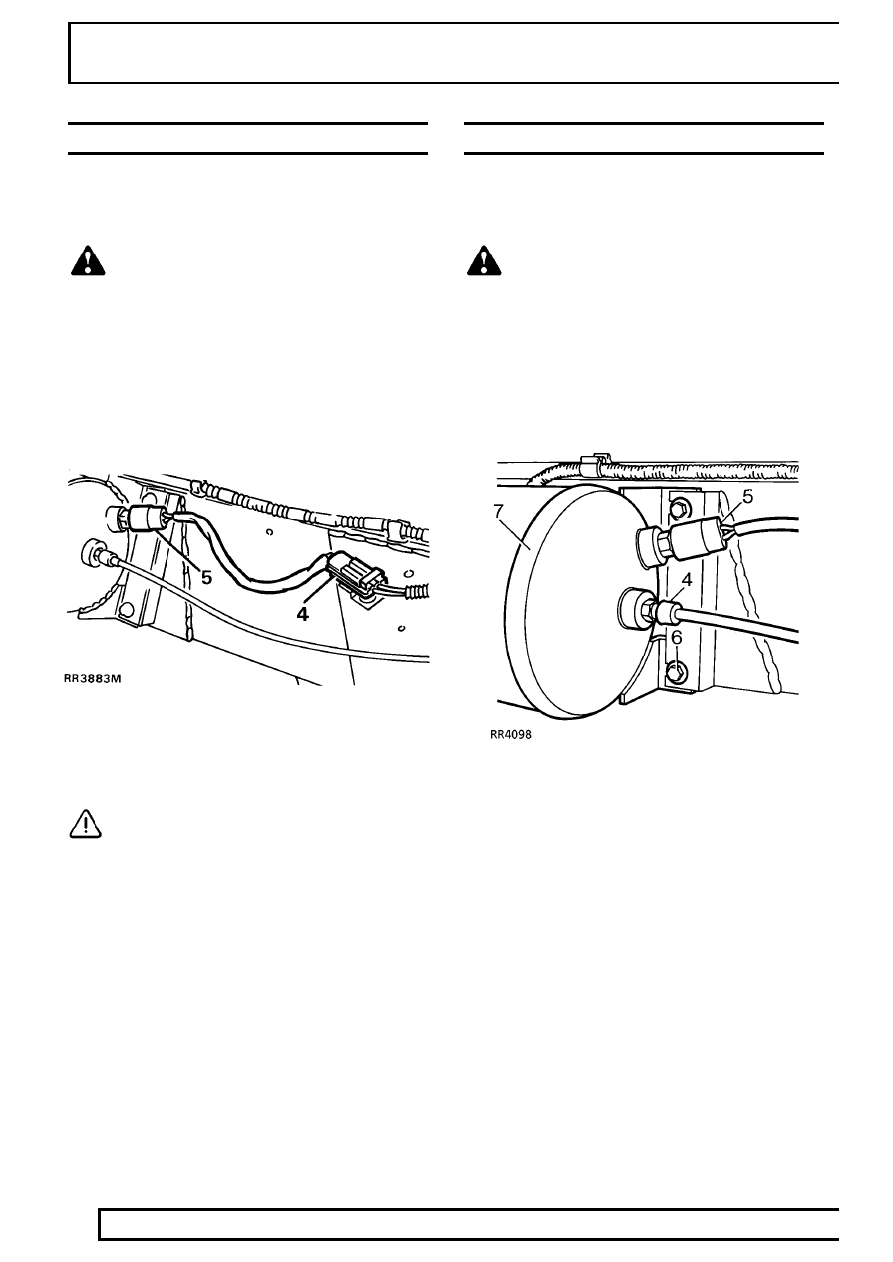
4. Disconnect pressure switch multiplug.
5. Unscrew and remove pressure switch.

CAUTION: Protect opening from ingress of
dirt.

Refit

6. Apply Loctite 572 to thread of pressure switch.
7. Fit pressure switch. Tighten to

23 Nm.

8. Connect multiplug and battery.
9. Start engine to re-pressurise system.

10. Attain standard ride height.
11. Leak test pressure switch.

See Adjustment,

Leak Test Procedure

AIR RESERVOIR

Service repair no - 60.50.03

Remove

WARNING: Air suspension is pressurised
up to 10 bar. Dirt or grease must not enter
the system. Wear hand, ear and eye safety

standard protection when servicing system.

1. Depressurise reservoir.

See Adjustment,

Depressurise System

2. Clean around air pipe connection and drain plug

with stiff brush and soapy water.

3. Open drain plug to release any residual

pressure.

4. Disconnect air pipe.

See Disconnect/Connect

Air Pipe

5. Disconnect pressure switch multiplug.
6. Release four fixing bolts.
7. Remove reservoir.

Refit

8. Fit reservoir. Tighten bolts to

24Nm.

9. Connect air pipe, fitting rubber boot.

See

Disconnect/Connect Air Pipe

10. Connect pressure switch multiplug.
11. Tighten drain plug to

70 Nm.

12. Start engine to repressurise system.
13. Leak test reservoir.

See Adjustment, Leak

Test Procedure

AIR SUSPENSION

13

REPAIR

ELECTRONIC CONTROL UNIT

Service repair no - 60.50.04

Remove

1. Remove front trim from right hand front seat

base.

2. Adjust seat rearward and upward.
3. Disconnect battery negative lead.

4. Release retaining clip from upper ECU plug.
5. Move plug in direction of arrow.
6. Detach hooked end of plug from retaining post.
7. Remove retaining screw.
8. Remove ECU from retaining clip.

Refit

9. Fit ECU into retaining clip.

10. Fit retaining screw.
11. Connect ECU harness plug. Ensure plug

retaining clip engages.

12. If fitting a new ECU, recalibrate height settings.

See Adjustment, System Calibration - Height
Sensor Datum

AIR HARNESS

Service repair no - 60.50.21

Remove

CAUTION: Thoroughly clean around all
connections before disconnecting air
pipes. Seal all exposed components

against ingress of dirt and moisture.

1. Place vehicle on a wheel free lift.
2. Remove wheels.
3. Remove air supply unit.

See Air Supply Unit

4. Disconnect air pipe from front left air spring.
5. Release front left chassis cable ties and clips.
6. Disconnect air pipe from reservoir.
7. Release back left chassis cable ties and clips,

leave clips in chassis.

8. Disconnect air pipe from back left air spring.
9. Release three rear chassis cable ties.

10. Disconnect air pipe from back right air spring.
11. Release back right chassis cable ties and clips.
12. Disconnect air pipe from front right air spring.
13. Release front right chassis cable ties and clips.
14. Remove air harness from vehicle.

Refit

15. Layout air harness, identifying routing and

connections.

16. Route air harness around chassis.
17. Remove sealing plugs, reconnect left front air

spring.

18. Secure left front chassis ties and clips.
19. Working around chassis.

AIR SUSPENSION

1

SERVICE TOOLS

RECOMMENDED EQUIPMENT

TestBook

Pressure test equipment

LRT-60-001

..........................

Pipe cutter

LRT-60-002

................................................

Leak detection spray

STC 1090

...................................

35 way ’pin out’ box

STC 644

.......................................

BRAKES

1

DESCRIPTION AND OPERATION

BRAKE SERVO UNIT

Description

The power assistance for the brake system is
provided by a twin diaphragm suspended vacuum
servo.

A ’Suspended Vacuum’ servo is one where, with the
engine running vacuum is present both sides of the
diaphragm or diaphragms when the brakes are fully
released or partially applied. The principal of having
vacuum both sides of the diaphragm has two main
advantages. First, it ensures instantaneous servo
response to the brake being applied or released and
second, it provides very accurate control of the
position of the diaphragm and therefore, the degree of
partial brake application.

At full pedal depression, vacuum is present in front of
the diaphragm with atmospheric pressure on the rear.

Operation

Brakes released

With the brakes released depression is present both
sides of the diaphragms, in chambers 1,2,3 and 4.
The chambers communicate by ports A, B, D via the
valve C which is shown fully released in RR3640M.


Content   ..  119  120  121  122   ..