Range Rover Classic. Manual - part 94


  Index      Land Rover     Range Rover Classic - service manual 1995 year


Search            


Content   ..  92  93  94  95   ..


Range Rover Classic. Manual - part 94


54

FRONT AXLE AND FINAL DRIVE

10

OVERHAUL

40. With seal lips trailing press axle shaft oil seal

flush into rear of housing. Grease lips.

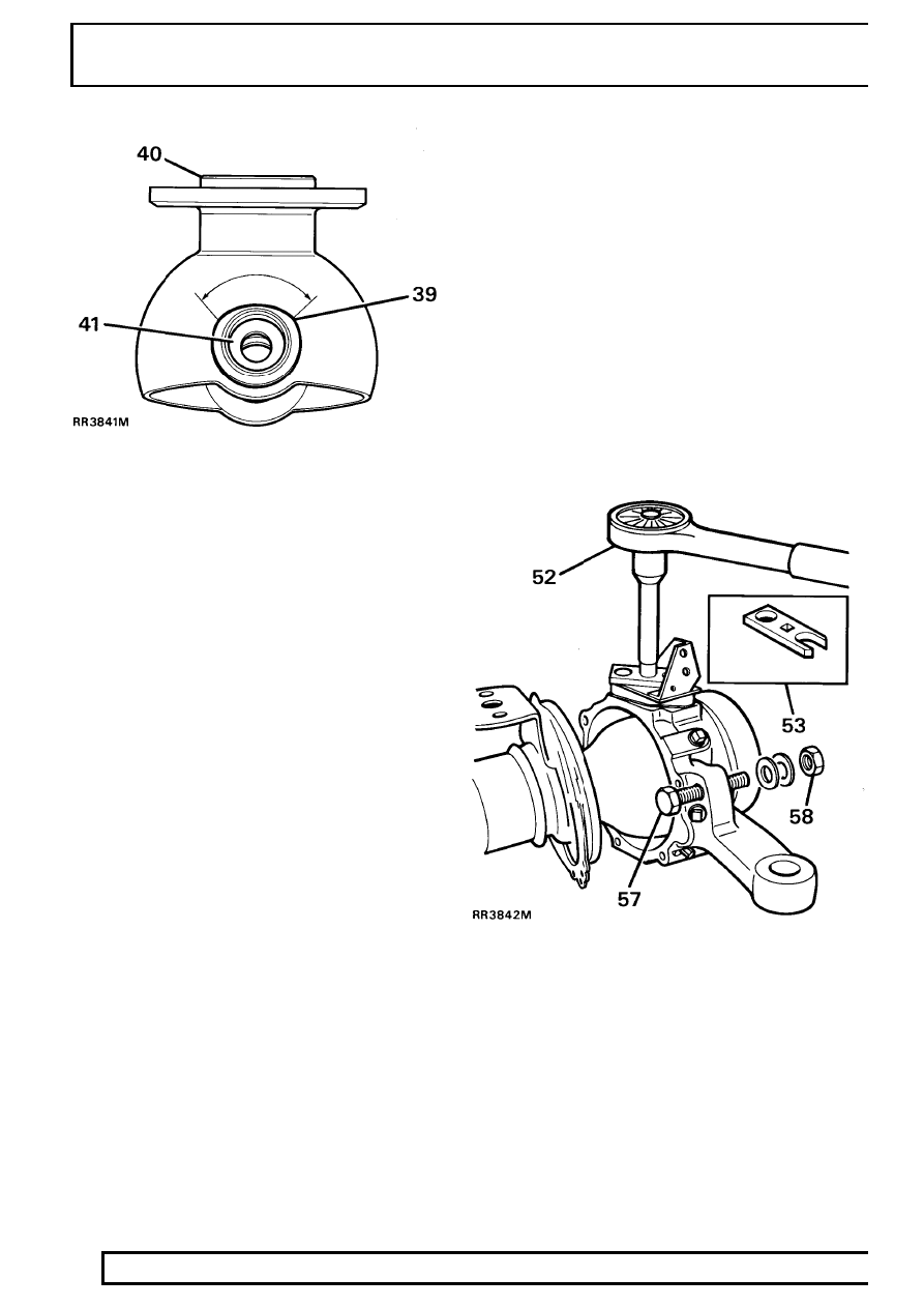
41. Fit new thrust washers and bearing into top

swivel pin bush.

42. Hang swivel pin bearing housing oil seal and

retainer plate over back of housing. Ensure they
are in correct assembly order.

43. Fit a new joint washer and secure swivel pin

bearing housing to axle. Starting with top fixing
dowel bolt. Tighten to

72Nm.

Fit swivel pin housing

44. Grease and fit lower swivel pin bearing to

bearing housing.

45. Place swivel pin housing in position over swivel

pin bearing housing.

46. Using a new joint washer, fit lower swivel pin

with lip outboard. Do not secure with screws at
this stage.

47. Fit a new sensor bush and new oil seal, lip side

leading to top swivel pin.

48. Lubricate with a recommended oil and fit top

swivel pin with existing shims.

49. Coat threads of top swivel pin bolts with Loctite

542. Fit bolts and jump hose bracket (do not
tighten).

50. Coat threads of lower swivel pin screws with

Loctite 270 and fit, together with damper and
shield bracket. Tighten to

25 Nm.

51. Tighten top swivel pin and brake jump hose

bracket securing bolts to

65 Nm.

Check and adjust preload on bearings

52. The preload on bearings to be 0,25 to 0,30 mm,

without swivel housing oil seal and axle fitted,
and reading from centre of swivel pin. The
torque required to turn swivel assembly from
lock to lock to be

2.0 to 2.8 Nm. Adjust by

removing or adding shims as necessary.

53. To take a reading use special tool LRT-57-024

torque test adaptor, with a torque wrench and
extension as shown.

54. Apply a recommended grease between lips of

swivel housing oil seal.

55. Secure oil seal with retaining plate and securing

bolts. Tighten to

11Nm.

56. Fit track-rod and drag link and secure with new

cotter pins.

57. Loosely fit lock stop bolt for later adjustment.
58. Fit brake disc shield.

FRONT AXLE AND FINAL DRIVE

11

OVERHAUL

Fit driveshaft and stub axle

59. Insert axle shaft, and when differential splines

are engaged, push assembly in fully.

CAUTION: Take care not to damage axle
shaft oil seals.

60. Place a new joint washer in position on swivelpin

housing to stub axle mating face. Coat threads
of stub axle bolts with Loctite 270.

61. Fit stub axle with flat at 12 o’clock position.

CAUTION: Ensure that constant velocity
joint bearing journal is butted against
thrust ring on stub axle. Before stub axle

is secured.

62. Place mud shield in position and secure stub

axle to swivel pin housing with six bolts and
tighten evenly to

65 Nm.

63. Fit brake jump hoses to brake jump hose

bracket.

64. Fit front hub complete assembly.

See Repair,

Front Hub Assembly

65. Check swivel pin housing oil drain plug is fitted.
66. Fill swivel assembly to correct level, with new oil.

See SECTION 10, Maintenance, Under
Vehicle Maintenance

67. Set steering lock stop bolts to provide a

clearance of 20mm.

See STEERING,

Adjustment, Steering Lock Stops

68. Fit ABS brake sensor.

See BRAKES, Repair,

Sensors - Front

54

FRONT AXLE AND FINAL DRIVE

12

OVERHAUL

FRONT HUB AND SWIVEL COMPONENTS

1. Brake caliper.
2. Mud shield.
3. Stub axle.
4. Joint washer.
5. Oil seal.
6. Bearing.
7. Brake disc shield.
8. Constant velocity joint.
9. Circlip.

10. Bush.
11. Inner driveshaft.
12. Top swivel pin and jump hose bracket.
13. Shim.
14. Swivel pin housing.

15. Joint washer.
16. Lower swivel pin.
17. Damper and shield bracket.
18. Thrust washer, ABS.
19. Bush and housing, ABS.
20. Swivel pin bearing housing.
21. Lower swivel pin bearing (and upper bearing non

ABS).

22. Oil seal.
23. Oil seal retaining plate.
24. Joint washer.
25. Oil seal, ABS.
26. Sensor bush, ABS.
27. Thrust bearing, ABS.

FRONT AXLE AND FINAL DRIVE

1

SPECIFICATIONS, TORQUE

TORQUE VALUES

NOTE: Torque wrenches should be regularly checked for accuracy to ensure that all fixings are
tightened to the correct torque.

Nm

FRONT AXLE
Hub driving member to hub

65

........................................................................

*

Brake disc to hub

73

.......................................................................................

Stub axle to swivel pin housing

65

..................................................................

*

Brake caliper to swivel pin housing

82

............................................................

Upper swivel pin to swivel pin housing

78

......................................................

*

Upper swivel pin to swivel pin housing ABS

65

..............................................

Lower swivel pin to swivel pin housing

78

......................................................

*

Lower swivel pin to swivel pin housing ABS

25

..............................................

*

Oil seal retainer to swivel pin housing

11

........................................................

Swivel bearing housing to axle case

73

..........................................................

*

Pinion housing to axle case

41

.......................................................................

Crown wheel to differential housing

58

...........................................................

Differential bearing cap to pinion housing

90

..................................................

Differential drive flange to drive shaft

47

.........................................................

Mudshield to bracket lower swivel pin

11

........................................................

Disc shield to bracket lower ABS

9

................................................................

Bevel pinion nut

130

........................................................................................

Draglink to hub arm

40

....................................................................................

Panhard rod to axle bracket

88

.......................................................................

Radius arm to axle

190

....................................................................................

Radius arm to chassis side member

190

.........................................................

NOTE: * These bolts to be coated with Loctite 270 prior to assembly.


Content   ..  92  93  94  95   ..