Range Rover Sport. Manual - part 18


  Index      Land Rover     Range Rover Sport - service repair manual 2005-2009 year


Search            


Content   ..  16  17  18  19   ..


Range Rover Sport. Manual - part 18


  CAUTION: Use a Torx socket to prevent the ball joint rotating whilst removing the nut.

  CAUTION: Note the position of the hardened steel washer. The hardened steel washer must be

installed between the stabilizer bar link and the upper arm. Failure to follow this instruction may result in
damage to the vehicle.

Remove the stabilizer bar link nut.


Discard the nut.

9
.

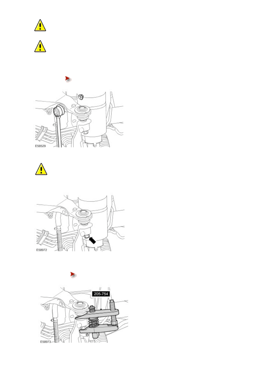
  CAUTION: To prevent the wheel knuckle falling outwards and disconnection of the halfshaft inner

joint, support the wheel knuckle.

Loosen the upper arm retaining nut. 

10 . Using the special tool, release the upper arm ball joint.


Remove and discard the retaining nut.


Remove the bolt.

12 . Remove the upper arm. 

Installation

All vehicles

1 . Install the upper arm.


Fit the bolts but do not fully tighten at this stage.

2 . Secure the brake hose and wheel speed sensor lead to the upper arm.


Tighten the bolt to 23 Nm (17 lb.ft).

3 . Connect the upper arm and wheel knuckle.


Install a new nut and tighten to 70 Nm (52 lb.ft).

Vehicles without Active Stabilization

4
.

  CAUTION: Make sure the hardened steel washer is installed between the stabilizer bar link and the

upper arm. Failure to follow this instruction may result in damage to the vehicle.

  CAUTION: Use a Torx socket to prevent the ball joint rotating whilst installing the nut.

Secure the stabilizer bar link.


Install a new nut and tighten to 175 Nm (129 lb.ft).

Vehicles with Active Stabilization

5
.

  CAUTION: Make sure the hardened steel washer is installed between the stabilizer bar link and the

upper arm. Failure to follow this instruction may result in damage to the vehicle.

Secure the stabilizer bar link.


Install a new nut and tighten to 175 Nm (129 lb.ft).

All vehicles

6 . Connect the height sensor link.

7 . Set the height distance, between the center of the halfshaft end, and the edge of the fender to 462 mm (18.19''). 

8 . Tighten the 2 upper arm nuts and bolts to 175 Nm (129 lb.ft).

9 . Secure the heat shield.

10 . Install the fender splash shield lower trim.

11 . Install the radiator access panel.


Tighten the bolts to 10 Nm (7 lb.ft).

12 . Install the wheel and tire.


Tighten the wheel nuts to 140 Nm (103 lb.ft).

Lower Arm (60.35.02) 

Special Service Tools

Ball joint separator 
205-754 (LRT-54-027) 

Halfshaft remover/replacer 
204-506/1 (LRT-60-030/1) 

Halfshaft remover/replacer 
204-506/3 (LRT-60-030/3) 

Retainers - halfshaft remover/replacer 
204-506/5 (LRT-60-030/5) 

Halfshaft installer adapter 
204-506-01 


Content   ..  16  17  18  19   ..