Frelander 2. Manual - part 158


  Index      Land Rover     Land Rover Frelander 2 - service repair manual 2006-2010 year


Search            


Content   ..  156  157  158  159   ..


Frelander 2. Manual - part 158


5

-

Bolt (2 of)

6

-

Variable tract valve

The intake manifold attaches to the cylinder head with 6 bolts and the oil pan with 2 bolts.

The manifold is capable of varying both intake tract length and plenum volume by means of 2 separate valves.

At low engine speeds, long intake tracts are utilized to provide optimum engine torque. Shorter tracts are used at medium speeds,
again, to optimize engine torque for the existing engine speed range.

At higher engine speeds the benefits of optimizing the tract lengths are outweighed by the necessity of maintaining an
appropriate supply of air to meet the engines requirements. Therefore, the plenum valve is opened to create a single, large
plenum volume to provide the maximum quantity of air to charge the engines cylinders.
For additional information, refer to: 

Intake Air Distribution and Filtering

 (303-12A Intake Air Distribution and Filtering - I6 3.2L

Petrol, Description and Operation).
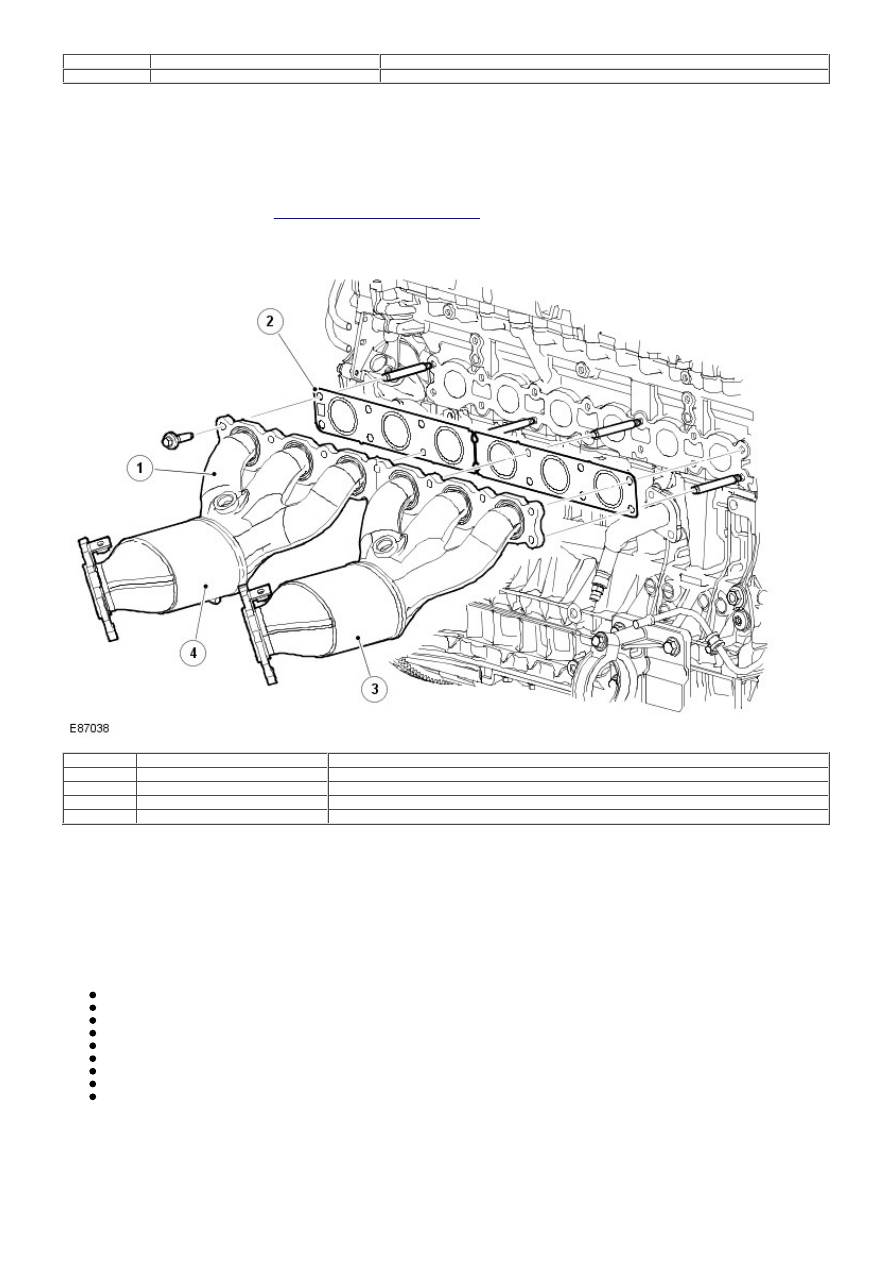
Exhaust Manifold

Item

Part Number

Description

1

-

Exhaust manifold assembly

2

-

Gasket

3

-

Exhaust manifold - cylinders 1 to 3

4

-

Exhaust manifold - cylinders 4 to 6

The exhaust manifold comprises 2 separate manifold assemblies. One manifold is used for cylinders 1 to 3 and the second
manifold is used for cylinders 4 to 6. The manifolds are sealed to the cylinder head with a gasket and secured with 14 bolts.

Each manifold comprises 3 fabricated branches, which merge into an integral catalytic converter. A threaded boss is positioned
where the 3 branches merge and provides for the fitment of a pre-catalyst Heated Oxygen Sensor (HO2S). The catalytic converter
outlets have offset flanges which mate with corresponding flanges on the front section exhaust system.

A bracket on each outlet flange allows for the attachment of an exhaust manifold heat shield.

CRANKSHAFT, BEDPLATE AND OIL PAN COMPONENTS

The crankshaft and oil pan components are:

Crankshaft and main bearings
Crankshaft vibration damper and cooling valve
Bedplate
Oil filter and cooler assembly
Oil pump assembly
Oil pick-up
Oil pan
Oil level gage
Starter motor

Crankshaft and Main Bearings

Item

Part Number

Description

A

-

Thrust bearing - position 6

B

-

Grooved main bearing - positions 2, 3 and 5

C

-

Main bearing - positions 1, 4 and 7

The crankshaft is made of forged steel and has induction hardened bearing surfaces. There are 2 types of aluminium main bearing:

W ith complete oil ducts for upper main bearings 2, 3, 5 and 6
W ith short oil ducts for all lower and 1, 4 and 7 upper main bearings

Due to missing counter-weights for cylinders 1 and 6 and selected counter-balancing of the entire crankshaft, main bearings 1, 4
and 7 are exposed to greater loads than the others. To reduce the load on the bearings, bearing shells with short oil ducts are
used. In addition, these main bearings have their own oil circuit where the oil is not distributed on to the connecting rod bearings.
The 6th main bearing also works as a thrust bearing.

A gear wheel is crimped to the rear edge of the crankshaft. The gear wheel drives the oil pump and the Rear End Ancillary Drive
(READ) timing gear.

The crankshaft has a viscous vibration damper located directly in front of the connecting rod pin for cylinder 1, i.e. located in the
actual cylinder block.

Crankshaft Vibration Damper and Cooling Valve

Item

Part Number

Description

1

-

Crankshaft vibration damper

2

-

Crankshaft vibration damper cooling valve

One of the remedies for obtaining a compact engine unit is to place the crankshaft vibration damper inside the engine block. The
damper has been positioned at the front of the crankshaft between the end and the connecting rod pin for the crankshaft for
cylinder 1.

Item

Part Number

Description

1

-

Front housing

2

-

Solid steel ring

3

-

Plastic bearing

4

-

Rear housing

The damper consists of a solid steel ring, placed in an enclosed housing filled with silicon fluid. The ring is radially journaled
through a plastic bearing. There are buttons on the front and rear side surfaces, 4 on each side. These buttons are axially
journaled.

The task of the damper is to even out fast unwanted increases and reductions in speed (i.e. crankshaft oscillations) and to give
the crankshaft a smoother operation.

When the rotation speed of the crankshaft increases or reduces quickly, the change in speed of the steel ring is delayed due to
the high viscosity of the silicon fluid. The function of the damper is based on the braking effect of the silicon fluid and the steel
ring's own inertia. When the ring moves in the silicon fluid in the damper housing, a large amount of heat is generated that must
be routed away.


Content   ..  156  157  158  159   ..