Discovery 2. Manual - part 584


  Index      Land Rover     Land Rover Discovery 2 - service manual 1999 year


Search            


Content   ..  582  583  584  585   ..


Discovery 2. Manual - part 584


REAR AXLE

OVERHAUL

51-13

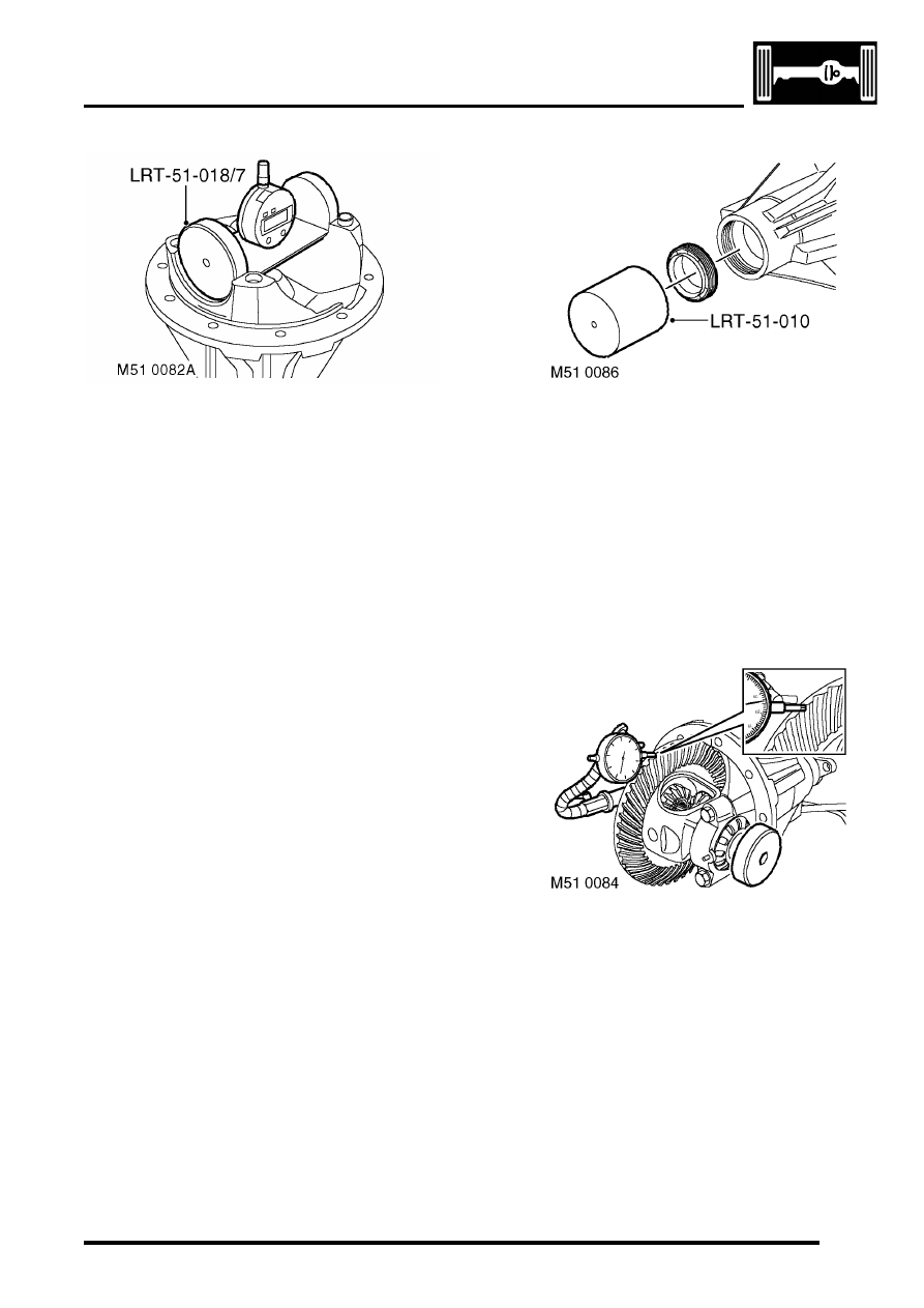
22. Align setting gauge LRT-51-018/7 to setting 

block, rock gauge to obtain minimum reading. If 
reading is lower than required reading, 
decrease shim size. If reading is higher than 
required reading, increase shim size.

23. Using LRT-51-003 to restrain pinion flange, 

remove bolt and washer.  Remove pinion 
flange.

24. Remove pinion, collect tail bearing and tail 

bearing shim.

25. Remove pinion head bearing outer race and 

shim. Discard shim. Ensure bearing race 
recess is clean and free from burrs.

26. Fit calculated shim, and using LRT-51-018/4 fit 

head bearing outer race.

27. Fit pinion, pinion tail bearing and tail bearing 

shim.

28. Fit pinion flange and bolt and washer. Using 

LRT-51-003 to restrain pinion flange, tighten 
bolt to 100 Nm (74 lbf.ft).

29. Rotate pinion in both directions to settle 

bearings.

30. Recheck pinion Torque to Turn, adjust if 

necessary.

31. Recheck pinion head height.
32. Using LRT-51-003 to restrain pinion flange, 

remove bolt and washer.  Remove pinion 
flange.

33. Discard bolt.

34. Using LRT-51-010 fit pinion seal.
35. Ensure spacer and tail bearing are correctly 

located.

36. Fit pinion, pinion flange and washer.
37. Fit new pinion flange bolt and tighten to 100 Nm 

(74 lbf.ft).

38. Lightly oil differential bearings.
39. Ensure spring dowels are fitted in bearing caps.
40. Fit differential bearing outer races and locate 

differential assembly into housing.

41. Fit bearing caps and tighten bolts to 10 Nm (7.5 

lbf.ft).

42. Fit adjusting nuts, tighten crown wheel side nut 

to 22 Nm (16 lbf.ft). Ensure opposing nut is 
loose. 

43. Position DTI to check crown wheel backlash. 

Adjust opposing nut to obtain correct crown 
wheel backlash.

44. Rotate pinion in both directions to settle 

bearings.

45. Measure in 3 places to obtain correct crown 

wheel backlash.

NOTE: Crown wheel backlash should be within 
0.076 mm - 0.177 mm (0.003' - 0.007').

46. Align adjusting nuts to next roll pin slot, do not 

loosen nuts to align slots.

REAR AXLE

51-14

OVERHAUL

47. Tighten bearing cap bolts to 90 Nm (66.5 lbf.ft).
48. Secure adjusting nuts with new roll pins.

49. Apply Prussian Blue to crown wheel teeth to 

check tooth contact.

50. Rotate pinion several times to obtain full  tooth 

contact.

51. A = Normal pattern, the drive pattern should be 

centred on the gear teeth. The coast pattern 
should be centred on the gear teeth but may be 
towards the toe. There should be some 
clearance between the pattern and the top of 
the gear teeth.

52. B = Backlash correct, thinner pinion shim 

required.

53. C = Backlash correct, thicker pinion shim 

required.

54. D = Pinion shim correct, decrease backlash.
55. E = Pinion shim correct, increase backlash.
56. Note assembly Torque to Turn when checking 

tooth contact. Total Torque to Turn should not 
exceed 10.85 Nm (8 lbf.ft).

Reassembly

1. Fit differential assembly.

FRONT AXLE

DESCRIPTION AND OPERATION

54-1

FRONT AXLE

DESCRIPTION AND OPERATION

Front axle component layout

Stake nut
Hub flange
Hub bearing
Steering knuckle
Drive shaft
Oil seal
Bolt
Bolt
Washer

10 Drive flange
11 Oil seal
12 Differential unit
13 Drain plug
14 Axle casing
15 Breather tube
16 Oil level plug
17 'O' ring

FRONT AXLE

54-2

DESCRIPTION AND OPERATION

Description

General
The front axle consists of an axle casing with a differential unit attached to the right of the vehicle centre line. A wheel 
hub is installed in a steering knuckle at each end of the axle casing and connected to the differential unit by a drive 
shaft.

Axle casing
The axle casing is of welded construction, with brackets on the casing exterior for attachment to the front suspension. 
Yokes at each end of the casing incorporate upper and lower ball joints for attachment of the steering knuckles.

A differential cover on the front of the axle casing contains an oil level plug for checking and replenishment of the 
differential lubricating oil. A magnetic drain plug is installed on the underside of the casing. An oil seal is installed in 
each end of the axle casing to prevent leakage past the drive shafts.

The interior of the axle casing is ventilated through a breather tube inserted in a red plastic sleeve in the top of the 
casing. The open end of the breather tube is located in the left rear corner of the engine compartment.

Differential unit
The differential unit is of the spiral bevel type, lubricated by splash oil. The unit consists of a differential carrier 
attached to a pinion housing. In the pinion housing, the pinion is splined to a drive flange which is secured with a bolt 
and washer. An oil seal prevents leakage past the drive flange.

Steering knuckle
The steering knuckles are mounted on upper and lower ball joints in the yokes at the end of the axle casing. A tension 
collet, in the lower mounting point of each steering knuckle, accommodates manufacturing tolerances to enable the 
correct tightening of both ball joints. Lugs are incorporated on the steering knuckles for attachment of the steering 
system drag link and track rod.


Content   ..  582  583  584  585   ..